The Hyundai Santa Fe Underbody LED Modification
| Original idea: | santamen |
| Author of procedures: | santamen |
| Installer / Testers: | santamen |
| Parts Supplier: | ebay, any auto parts store |
| Images provided by: | santamen |
Introduction / History
| Adding lights underneath the vehicle can add a unique show car feel and add a personal touch. This guide shows you just one way of doing this. |
|
Disclaimer
|
Difficulty level / scale: On a scale of 1 - 10
| Easy | Difficult |
| 1 | 2 | 3 | 4 | 5 | 6 | 7 | 8 | 9 | 10 |
| X |
Tools and materials needed:
| Philips screwdriver |
| wrench |
| Drill |
| Jack and Jack stands |
| Putty |
| Electrical tape |
| Optional: |
| Dremel tool |
| Sand paper |
| dielectric grease |
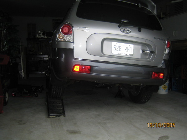
Step 1: Lifting the Santa Fe using a garage (floor) jack..
(Click on images to open up in
full size)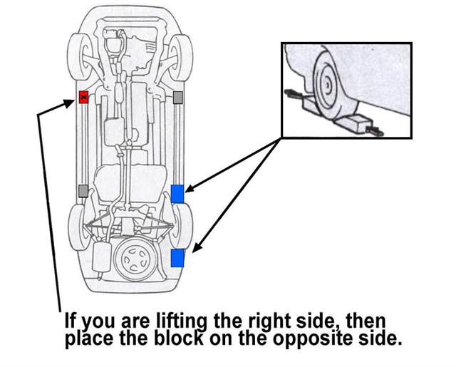 |
While the
modification can possibly be performed without jacking up the vehicle,
jacking it up will make it much more easier. |
(Click on images to open up in
full size)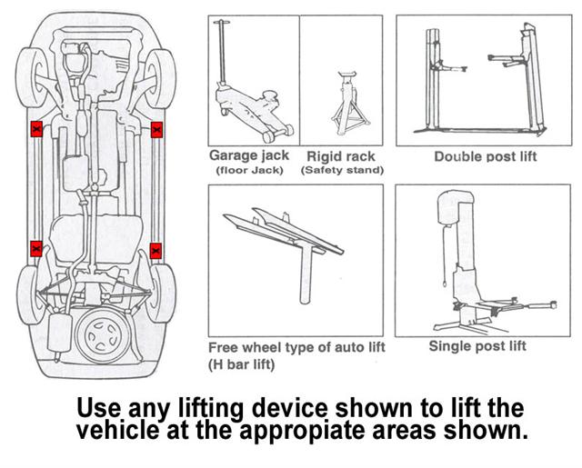 |
Then place the jack at the appropriate place according to this diagram.
|
|
(Click on images to open up in
full size) |
Then jack up the vehicle. |
Step 2: Drilling and attachments.
(Click on image to open up in full size)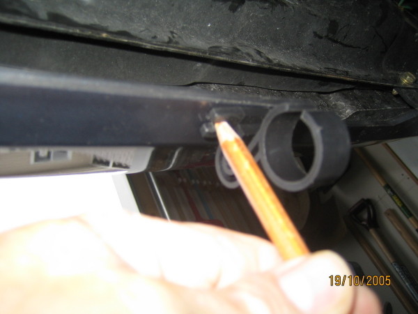 |
Go underneath and mark where you want to place the LED Bars |
(Click on image to open up in full size)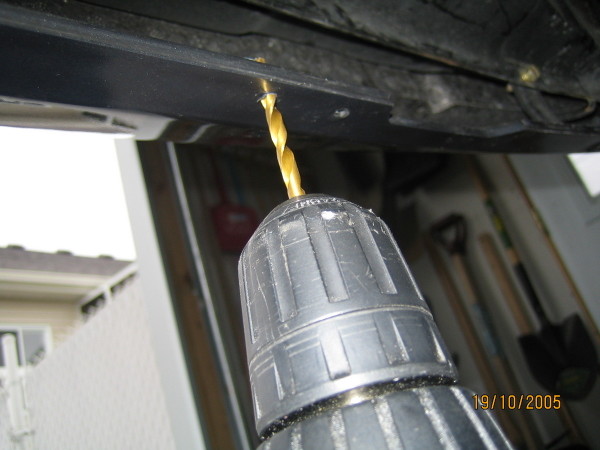 |
Drill at the places you marked. |
(Click on image to open up in full size)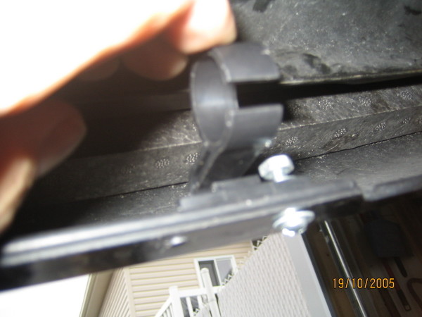 |
Install the bracket that was supplied with the LED bar. |
(Click on image to open up in full size)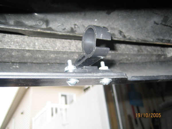 |
Screw in the bolt and nut and tightened. This is how it should look like. |
(Click on image to open up in full size)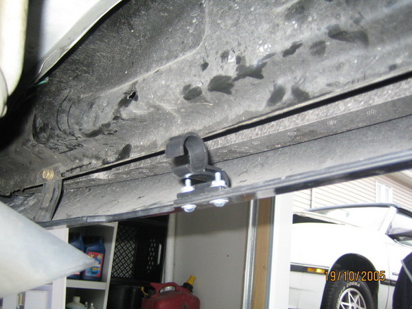 |
If you have the vehicle on a hydraulic lift or on four jacks stands, then do the same for the other side. Otherwise continue. |
(Click on image to open up in full size)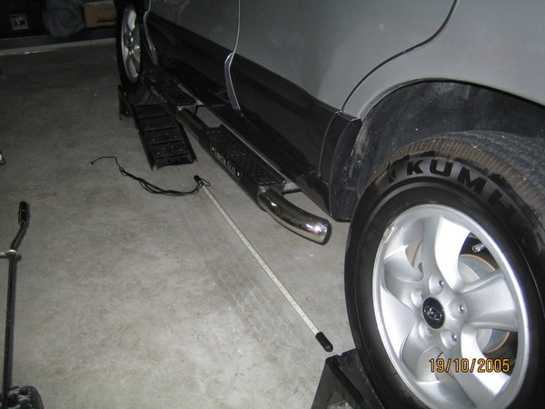 |
Place the LED bar close by. |
(Click on image to open up in full size)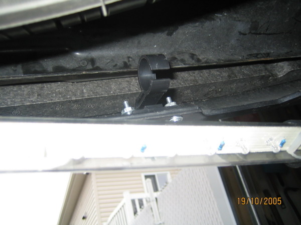 |
Take the LED bar and clip it inside the bracket. |
(Click on image to open up in full size)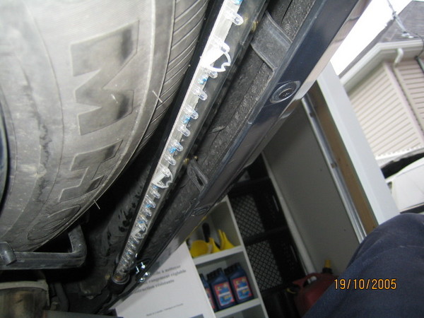 |
The LED bar after its installed on the clips. |
Some un-detailed views of the previous steps:
| Vehicle on jack stands | Light bar installed | Light bar installed - another view | ||
 |

|
 |
Step 3: Pre-testing.
(Click on image to open up in full size)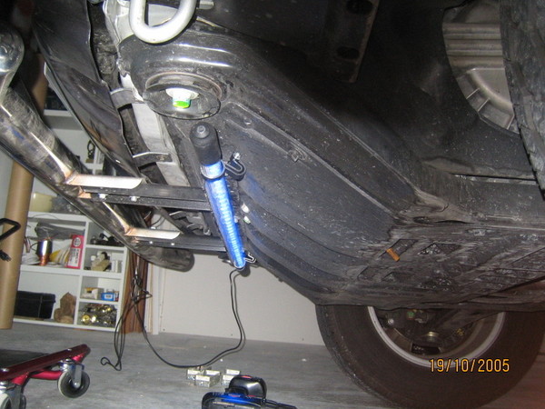 |
Attach the power cables to the LED bars and test them before installing the cables. |
(Click on image to open up in full size)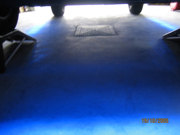 |
Testing the view from beneath (front). |
(Click on image to open up in full size)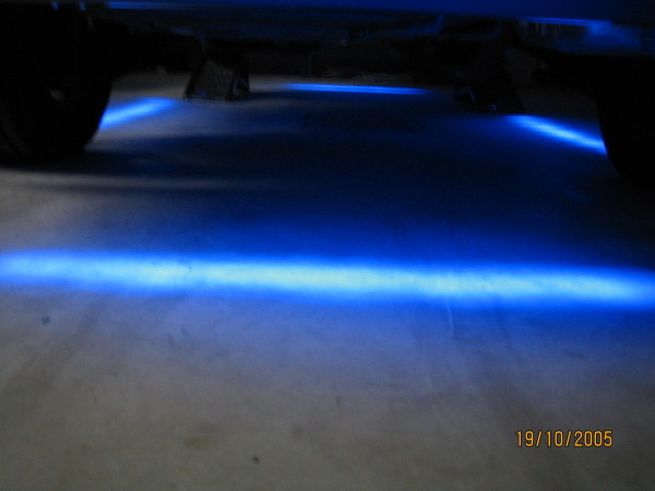 |
Testing the view from beneath (rear). |
Step 4: Preparing the cabin where the cables will run through.
(Click on image to open up in full size)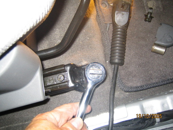 |
I decided to pass all the wires under the passenger seat (it was the best and easiest place to work). I started by removing the passenger seat. I unbolted the seat in front. |
|
Click on image to open up in full size) 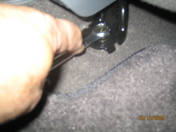 |
Unbolt the rear bolts of the front passenger seat. |
(Click on image to open up in full size)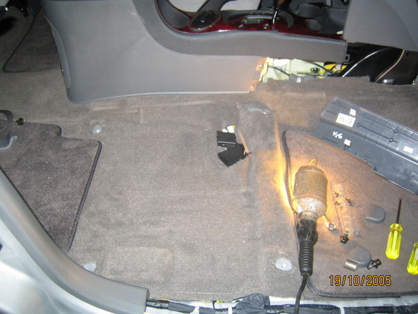 |
Remove the seat. |
|
Click on image to open up in full size) 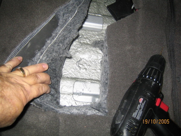 |
At this point, you can elect to remove the carpet to get to the underlying frame or cut the carpet. Cutting the carpet would not matter since the cut will be performed underneath the seat area and will not be viewable once the seat is put back into place. |
(Click on image to open up in full size)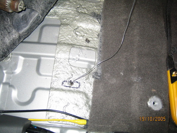 |
Once you have the carpet out of the way, find a place to
drill. Measure carefully from the edge of the door way to the place you
intend to drill at. Then go underneath and measure and check to see that you
are not going to hit anything. Then drill a tiny hole large enough to insert a steel wire hanger through to see that nothing is in your way . |
|
Click on image to open up in full size) 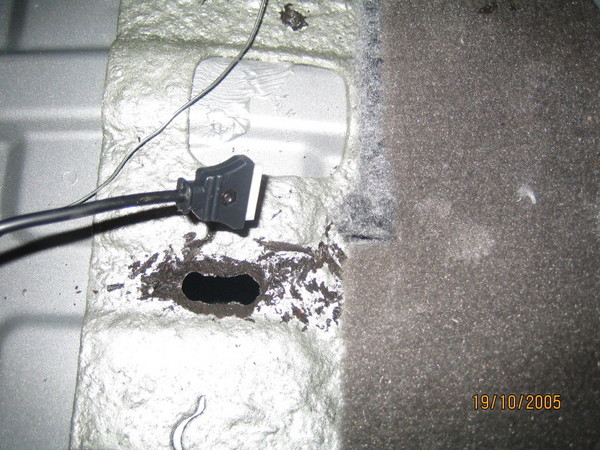 |
After that drill a hole big enough that would allow the connectors to go through. You may need a dremel tool or sand paper to take out the shivers on the edge. This prevents you from getting cut or cutting the cables when you run them through. |
(Click on image to open up in full size)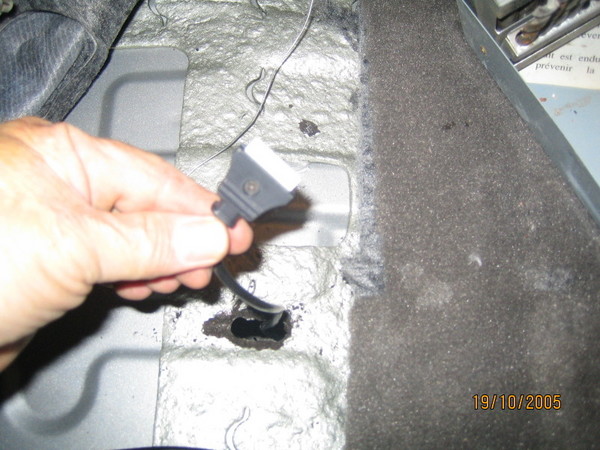 |
Start bring in all 4 connectors through the hole into the cabin area. |
|
Click on image to open up in full size) 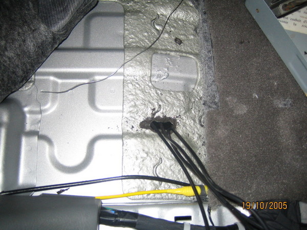 |
This image shows all 4 connectors that have gone through the hole. |
(Click on image to open up in full size)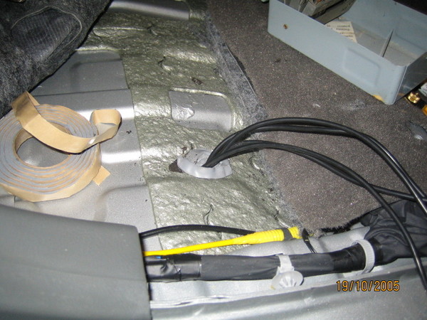 |
Apply some dielectric grease at the edges of the hole to prevent corrosion. Then put putty around the hole to prevent any water from going inside. |
|
Click on image to open up in full size) 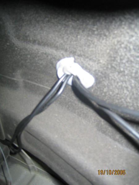 |
Do the same for the underside. |
(Click on image to open up in full size)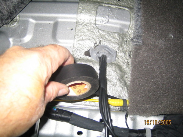 |
Start to wrap the cables with electrical tape. |
|
Click on image to open up in full size) 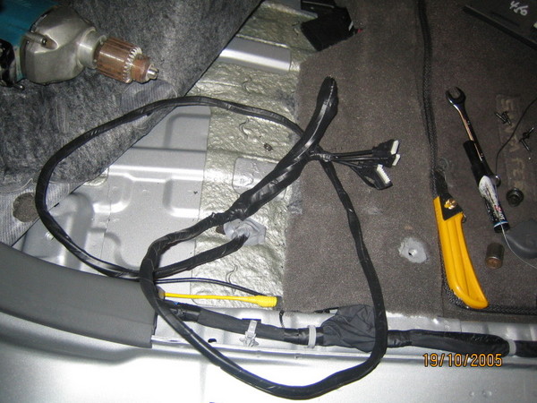 |
Continue wrapping the cables in electrical tape up to about 2-3 inches from the connectors ends. |
Step 5: Preparing the middle console.
(Click on image to open up in full size)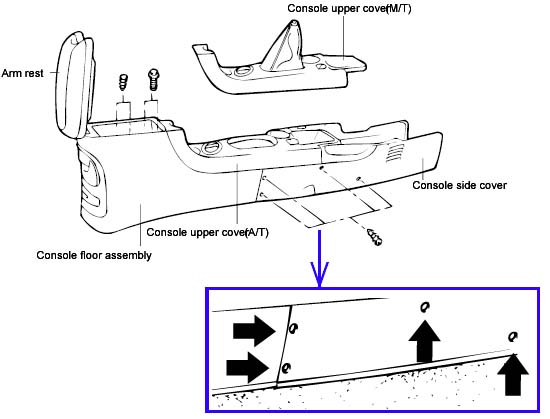 |
Remove the screws holding the console side cover. |
|
Click on image to open up in full size) 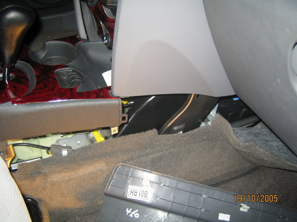 |
Now remove the console side cover. |
(Click on image to open up in full size)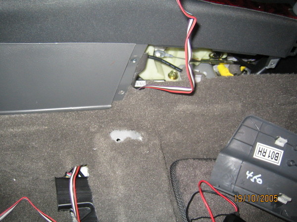 |
Pass the wires under the carpet and route them to the console. |
|
Click on image to open up in full size) 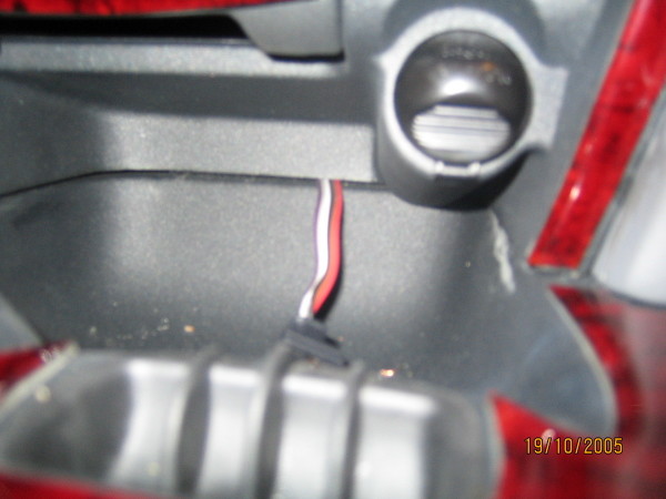 |
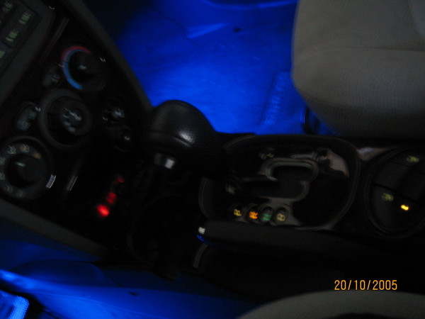
The LED bar kit has a control box that can be placed
anywhere, and the installer decided to place it under the ashtray. The wires were routed to the ashtray area. |
(Click on image to open up in full size)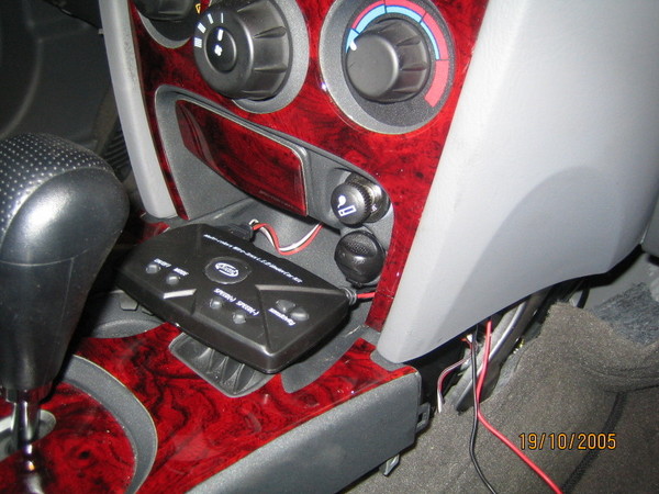 |
The control box connected to the wires. |
|
Click on image to open up in full size) 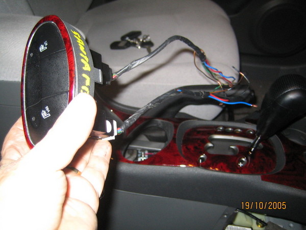 |
The unit has a separate On/Off switch and the installer attached them to the Electric heat seat switches. (He obtained the switches from a scrap yard since he did not have them and uses them to control other light sources. If you already have the electric heat seat switches (LX model) then you will need to select another power source. |
(Click on image to open up in full size)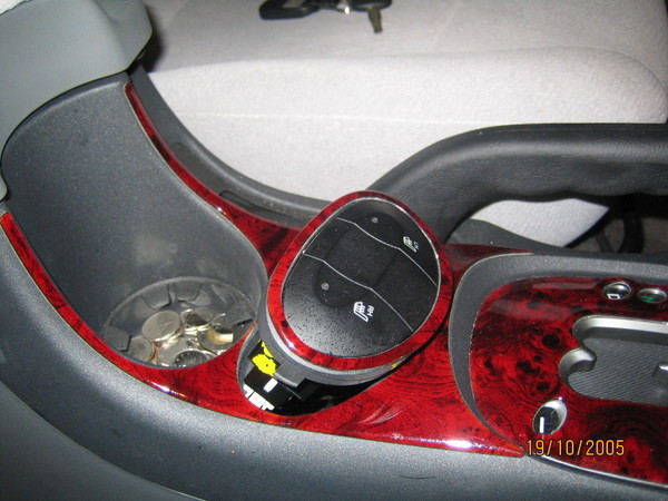 |
Placing back the electric seat heat switches. |
Step 6: Reinstall all components.
|
Click on image to open up in full size) 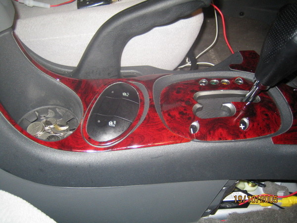 |
After all the connections are done, reinstall all components. The Electric heat seat switches. |
(Click on image to open up in full size)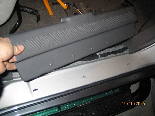
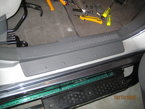 |
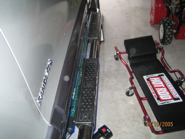
The Floor step |
|
Click on image to open up in full size) 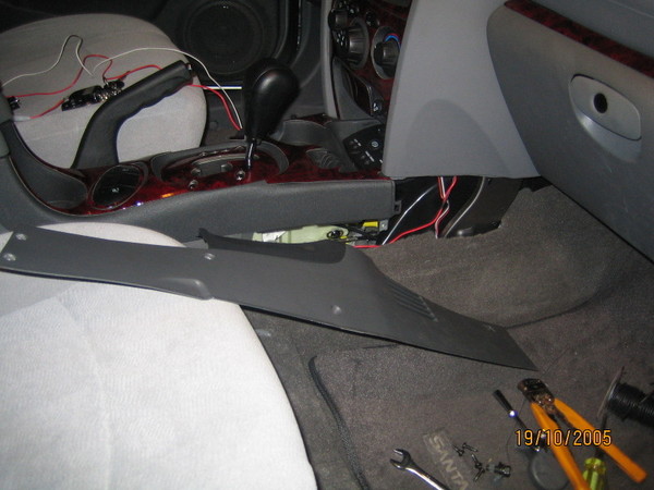
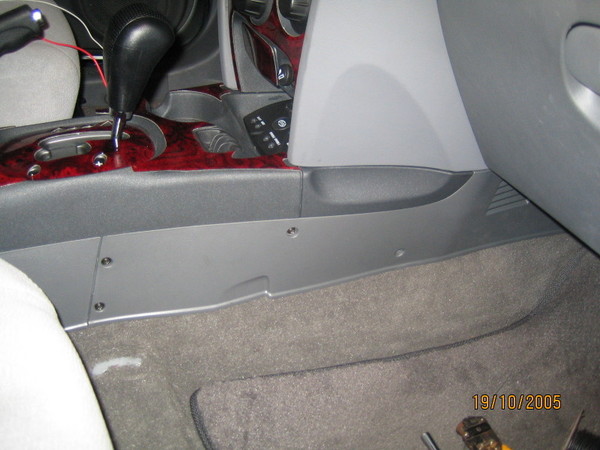 |
The side console panel. |
(Click on image to open up in full size)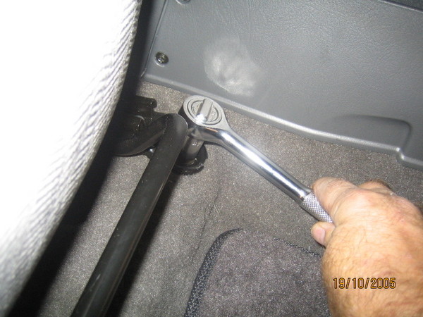 |
Place back the passenger seat. |
|
Click on image to open up in full size) 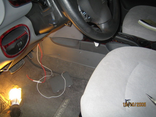 |
Connect the power and ground to the fuse box. |
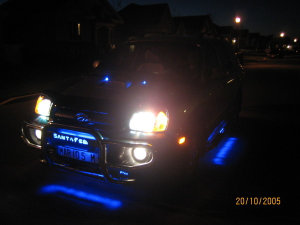
Final Views: (Click on image to open up in full size)
| Control box | Interior view | Exterior view | ||
 |
|
|
||
This site was last updated 02/08/06