Turning your
Hyundai Santa Fe Side Markers into
Park/Signal lights Modification
Original idea:
twospirits
Idea
Enhancements:
nomogm and krcooper
Testers:
twospirits
Author:
twospirits & nomogm
Images by:
twospirits
Introduction
/ History
The Hyundai Santa Fe
comes with two side markers. The purpose of side markers is to enable a
driver to see another vehicle that is approaching at an angle at night or at
a stand still and to see it early enough that the other driver can stop in
time to prevent a collision or at least slow down to reduce the severity of
the collision. The addition of side markers in vehicles was started in Jan
of 1968 and has since been in every vehicle on the road. Unfortunately some
of these markers are just that, markers. Some automakers have incorporated
making them signal lamps as well. The Hyundai Santa Fe has inboard mounted
signal markers in the combination lamp, which are not visible from the side.
The vehicle has side markers but are the type that are just static and do
not signal. Side markers that signal give the added security that any
pedestrian or other vehicle on your side will realize your intention of
turning. This reduces your chances of getting into an accident. For these
reasons, I decided to modify the current markers into signal ones. The
location of the markers on the Santa Fe depends on the model and or location
where purchased. In the USA they are on the front side fenders. In Europe,
they are placed up near the metal close to the mirrors. Regardless of
location this modification will convert these static non directional signal
markers into fully functional signal markers.
2 x 2 feet
color wire (14-18 gauge) preferably Yellow.
Optional
items:
Electrical
Tape
Test light
Pliers
Time to perform modification:
First set of lights
30-40 min
Second set of lights
20-30 min
Total time for mod:
1 Hour
Step 1: Removing and preparing the Combination lamp.
First off, you should disconnect the negative battery terminal.
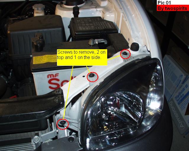
The Combination lamp is attached to the body by 3 screws. Two of them are on
top of the headlights and one to the inner side of it. (See pic 01). After
you unscrew the screws you will need to insert one hand behind the lamp and
push towards you to dislodge it from the body to give you more flexible
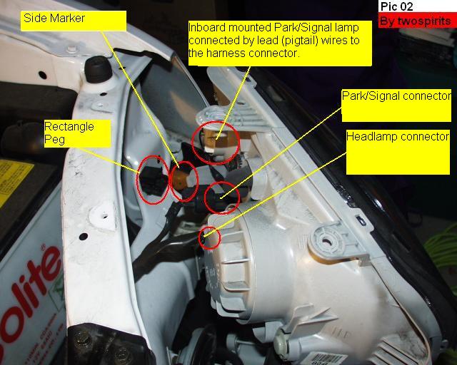
room. There is a rectangular peg that aligns it to the body and it really is
tight. (See pic 02).
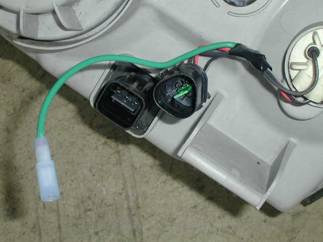
Once the combination lamp is detached from the body, you will see the two
wiring harness connectors. (See pic 02). One is for inboard mounted
park/signal light; the other is the headlamp light. Detach these wire
harness connectors from the combination lamp by pressing down on their
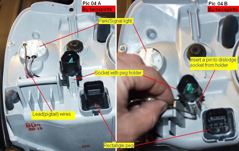
clips. The Park/Signal harness connector connects to a lead (pigtail) wire
(see pic 04 A) directly to the Park/Signal light which stays attached to the
combination lamp housing for the time being.
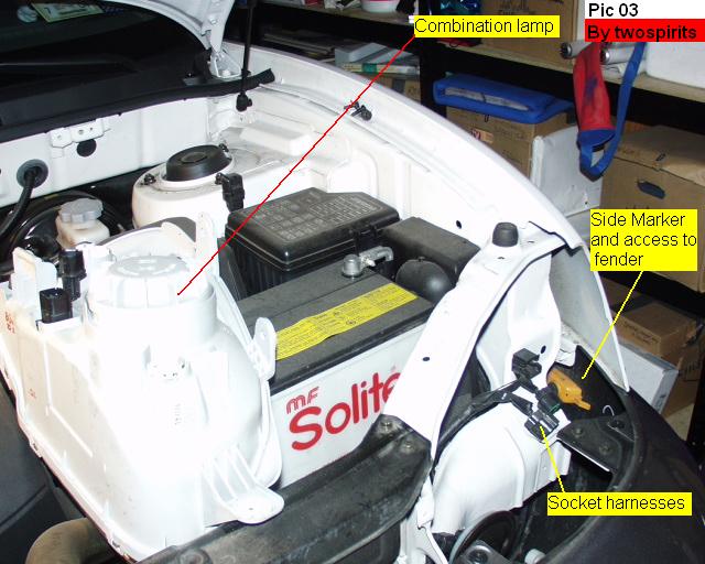
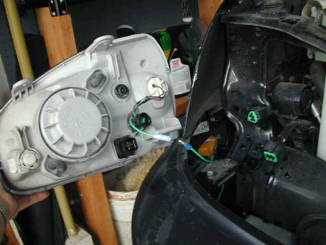
After you
remove the combination lamp you will see the side marker from the opening.
This opening is where you will be able to fish the wires later on. (See pic
03).
Place the
combination lamp housing in a comfortable area to work with. Turn the
housing so that the big round knob is to your right. This will allow you to
see the peg holder that holds the lead (pigtail) wire connector to the
housing. (See pic 04 A) You need to take out the connector in order to have
ample room to work with it. (See pic 04 B).
I used a hex screw to push in the hole to pull the connector out. You may
find something else that is better. Once you dislodged it put it to the side
to work on it later.
Step 2: Removing and preparing the Side Marker.
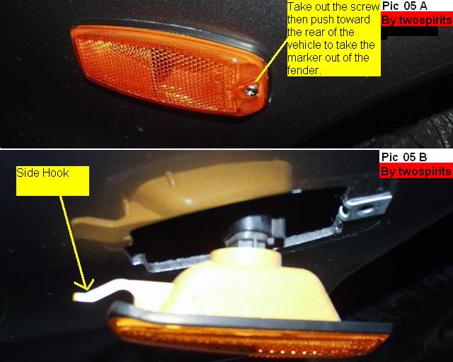
The side
marker is attached to the fender by one screw and a hook. (See pic 05 A)
Unscrew the screw and push the marker gently towards the rear of the vehicle
then towards you.
Once the marker is out you will notice the hook. (See pic 05 B).
Once the
marker is detached from the fender, detach the marker light from the side
marker housing. Set the housing to the side.
Note: My
left marker came out without any problems; the right one was another story.
It refused to unscrew. At this point I had to take my dremel tool and cut
the screw from the inside to be able to take it out. Use your better
judgment if a situation like that comes up.
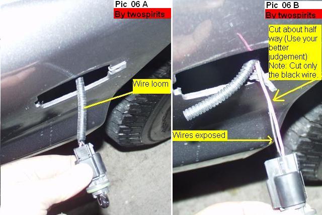
The side
marker has two color coordinated wires. Depending on which one you are
working on, the color is different. The left marker has one black and one
pink wire. The right marker has one black and one pink w/ black stripe wire.
These wires are covered in a wire loom that is also wrapped in electrical
tape. (See pic 06 A) Take off the electrical tape. The wire loom will then
be exposed. This loom is cut open on one side; carefully take out the wires
out of the loom.
As you
can see there is not that much room to work with. At this point you will
need to cut the Black wire only. Make sure you leave enough room to be able
to work on both ends of the cut section. I chose to cut it at the halfway
point. (See pic 06 B) Leave the other wire alone.
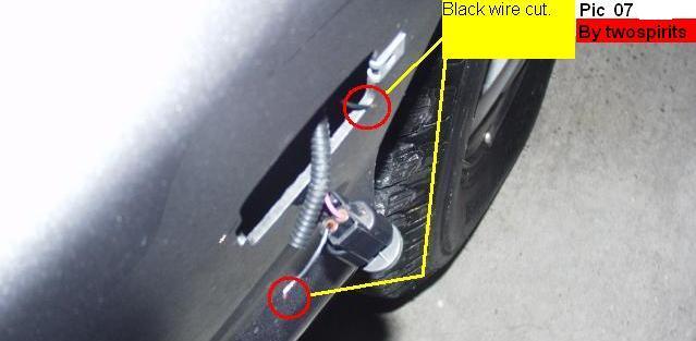
Picture # 7 shows you
the cut black wire. The pink one is left alone.
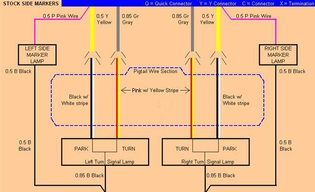
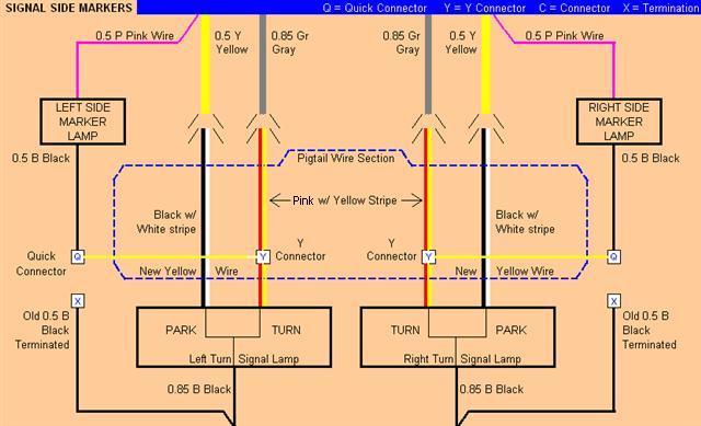
Step 3: Wire Color coordination.
Both the side marker and
the combination lamp have color-coordinated wires. These colors are outlined
in the 2002 Hyundai ETM (Electrical Troubleshooting Manual). But the colors of the wires that consist of the lead (pigtail)
wires (mentioned in step 1 above)
are not in the ETM.
The following diagram
shows the original and new connections along with the colors of the pigtail
wires. The original diagram can be located at
https://dcsonline.hyundaidealer.com/customer/tech_info/tech_sevice_main.html
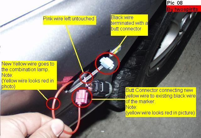
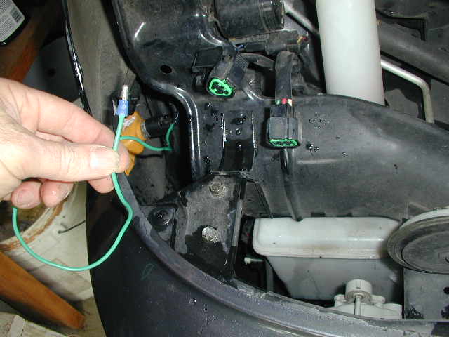
You will now terminate the black wire that leads back into the chassis by
using either a quick connect connector or electrical tape. This will protect it from
touching any metal section of the vehicle. Does not matter since that wire
is the ground anyway.(See pic 08).
You will take about 2 feet in length of the new wire (Yellow) and fish/route it
through the fender side marker hole to the engine bay area (see pic 03
above). You will attach this new yellow wire to the cut black wire with a
quick connect
connector. . (See pic 08).
Note: The new yellow wire looks red
in the photo.
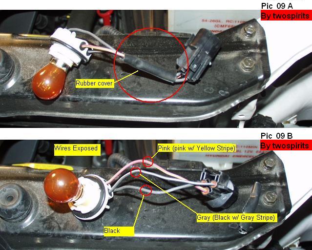
Step 5: Wiring the Combination lamp.
Take the
lead (pigtail) wire harness and take out the rubber cover of the wires. I
used an utility knife.
You may
want to remove the light to prevent damage to it. (See pic 09 A)
Once you
have the rubber cover off you will have better access to the three wires of
the lead (pigtail) wire harness. (See pic 09 B)
Both the left and right lead (pigtail) wires have the same colors. Black,
Black with White stripe, and a Pink with yellow stripe wire. (See wiring
diagram above) You will be connecting the new yellow wire from step 4 above
that’s coming from the side marker to the Pink w/ yellow stripe wire only.
(See pic 10).
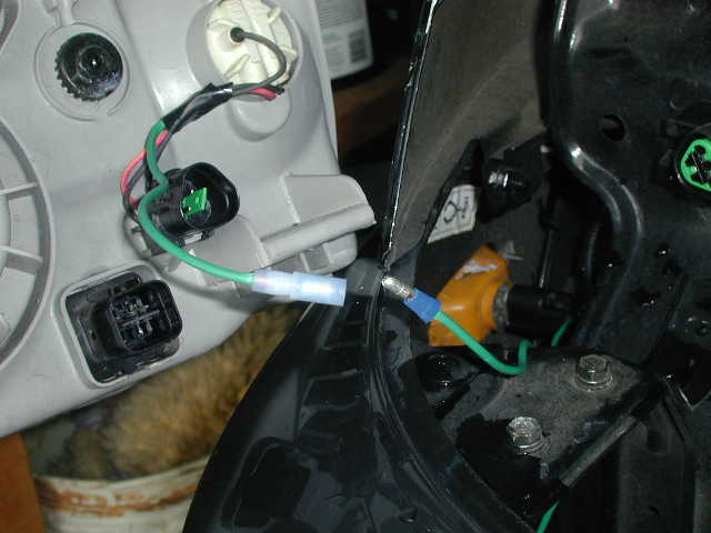
Doing the above step will
have the headlamp permanently attached to the wire of the side marker. The
best way would be to allow for quick way to disconnect the lamp from
the wires. One way to hook this up
is to have a short (4-5") piece of wire with a quick disconnect
connector (female on the end of that - male on the end of the wire attached
to the side marker light extension wire) attached to the pigtail
that plugs into the headlight housing. This will allow for quick, easy
complete removal of the headlight from the vehicle - without having one wire
dangling and still attached to the side marker lights.
(pics and above suggestion provided by forum member krcooper.
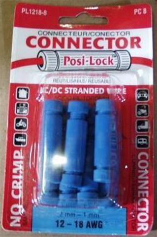
Another way would be to have the
connectors that allow you to screw the wires in. This is quick and the
connectors can be used over and over. I now end up using these type of
connectors in all my projects. They are Swenco (#PL1218-8) Posi-Lock
Connectors and are available at your local Autozone or auto parts store.
Step 6: Test the lights.
At this
point you should reconnect the wiring harnesses to the combination lamp.
Reconnect the negative battery cable and insert your ignition key and test
the lights.
They should at this point work and perform the following functions.
1-
Should come on when you turn on your parking lamps.
2-
Should flash as directional signals with parking lamps are on
or off.
(They will work in different / alternating flashes. ex: When
the parking light goes on the marker goes off and vice versa.)
3-
Stay on when using the hazards.
Step 7: Perform the steps on the other side.
Perform
steps 4 through 6 on the other side of the vehicle and retest them.
Step 8: Reinstall all the lamps.
Reattach
all lamps back into their housings and enjoy your new signal marker lights.