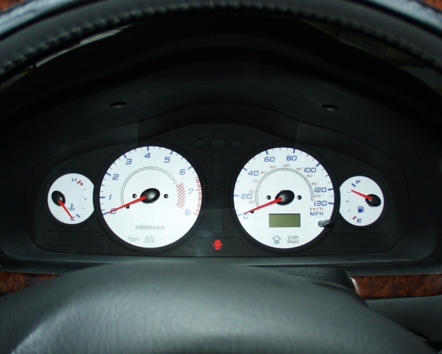
The Hyundai Santa Fe comes with a OEM stock instrument panel gauges that
have white numbers/letters on a black background. These gauges are fine but
there are other aftermarket gauges that have white facing which helps the
driver see them in the daytime and which are either blue or green at
nighttime. These aftermarket gauges are commonly know as Euro Reverse
Indiglo Glow Gauges or Indiglo Gauges.
These gauges can be obtain from numerous sources on the internet. One such
place is ProCarParts. They sell these gauges both on their website as well
as on Ebay. The prices range from $23.95 USD on up depending which site you
obtain them from.
This install guide shows you how to install these aftermarket gauges
specifically for the Santa Fe.
This
write up is basically an update version of the outstanding Install guides
provided by Santa Fe Forum (SFF) member Sac D on 08/09/2002 which is an
updated edit of the one created by SFF member GM Typhoon on 07/13/2002.
Special thanks go out to both of them as well as to the other Santa Fe Forum
members that provided ideas and enhancements to this outstanding
mod/install.
Note:While
this step by step instruction is a bit long, and might scare off some
readers thinking of doing this mod, but I hope that the level of detail
might entice the reader in knowing that every possible scenario is covered
and detailed. If I were to condense it, some necessary information might be
omitted and thus not provide the reader with the necessary details in doing
this modification.
Clicking on any of the pictures below will
open up a second window with the picture in question at full size.
Phillips
#1 screwdriver (no longer than 6 inches long)
Phillips #0
screwdriver (no longer than 6 inches long)
Exacto knife
Pencil
Wire
Stripper
12mm socket
wrench
Optional
Items
2 small
screws
Electrical
Tape
Rubbing
Alcohol
8" Black
wire
1 Posi-Twist
connector
1 Blue butt
connector
Dremel Tool
Superglue
gel or Liquid Contact Adhesive
Time to install item:
Total time for mod:
120
min
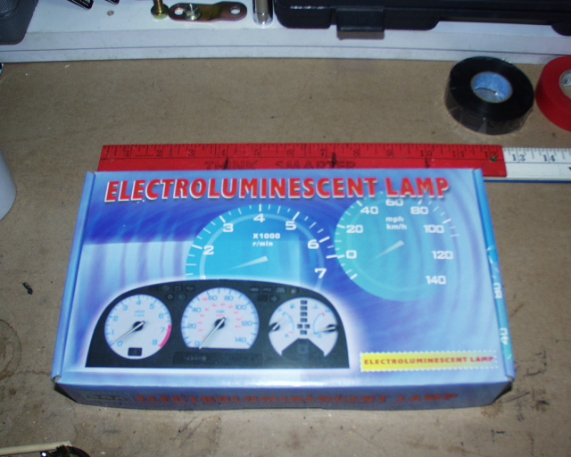
Source, item
and packaging
The item ProCarparts is
shipped in a box that looks like this. Some of them are also shipped not in
a box but rather in a bubble wrapped envelope. Either shipped item is the
same.
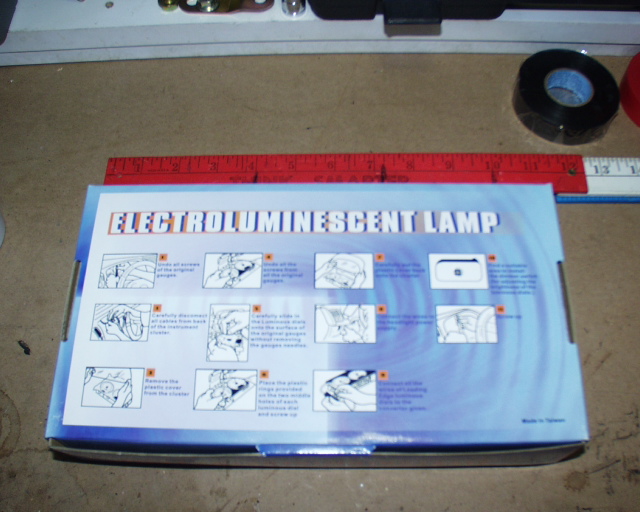
The back of the box has the
generic instructions which can be used but are not as detailed or fine tuned
for the Santa Fe.
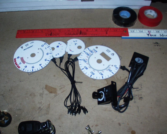
These are the items out of
the package.
You have the 4 gauges,...
The Temperature, Tachometer, Speedometer and Fuel gauge.
Also included are the 4 EZ-connecting wires, the transformer, the
combo dimmer rheostat with blue green/toggle switch and the 2 power/ground
lead wires.
Also included in the package is a instruction sheet which is basically
unusable since it is a translated word by word instruction sheet that was
originally written in Chinese. (The items are made in Taiwan.)
Step 1:
Removing the stock OEM Instrument Panel Gauges.
Set the
drivers seat to its furthest setting away from the steering column.
Set the height of the steering wheel column down to the lowest it can go.
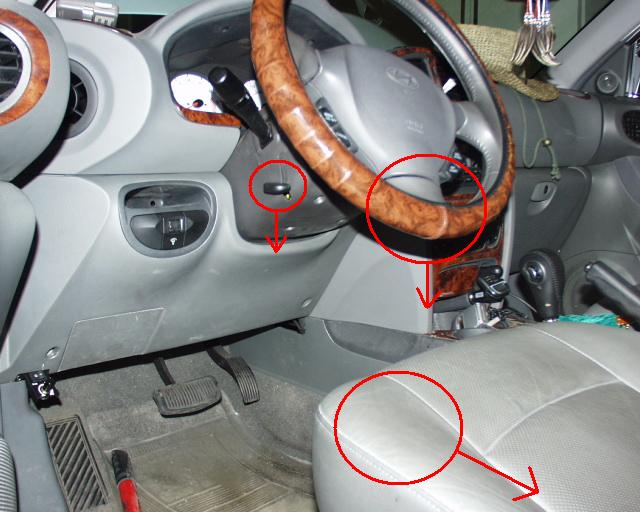
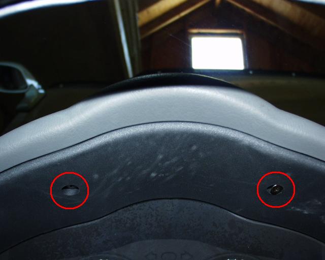
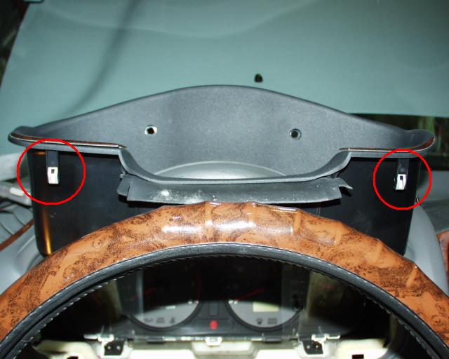
Remove the
instrument cluster fascia panel by removing the 2 screws holding it in the
top of the dash. The instrument cluster fascia panel is the plastic cover
underneath the dashboard overhang.
Make sure you use a good screwdriver and one that is no longer than 6 inches
in length, because you will not get in there and be able to unscrew the
screws.
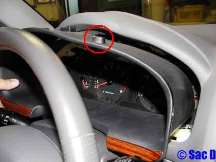
You need to
flex the fascia a bit to get it to pop out.
(The Fascia has two bumps on the top where the screws were and two plungers
on the bottom.)
This pic shows the plungers underneath it.
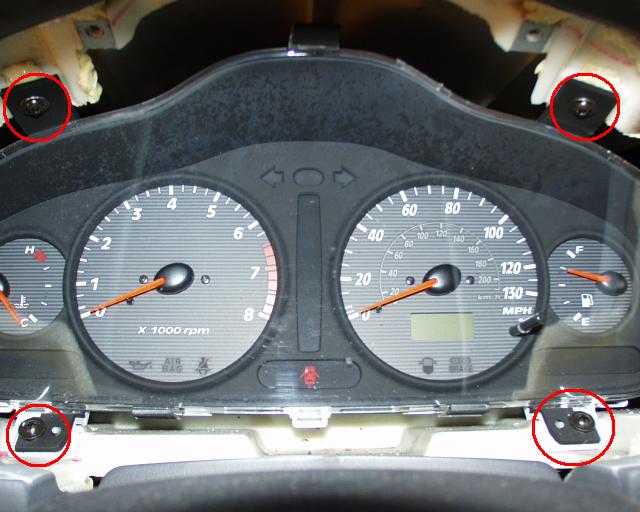
Remove the 4
screws holding the Instrument cluster and remove it by gently rolling it out
towards you. These 4 screws are also in there really tight, so don't rush,
be careful and use plenty of controlled torque to remove them.
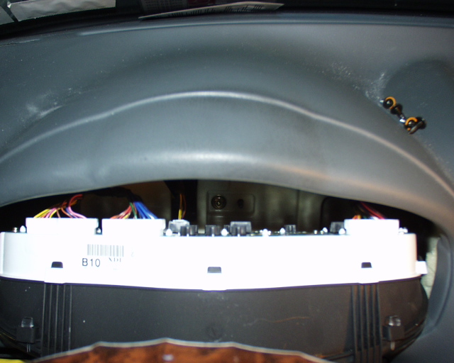
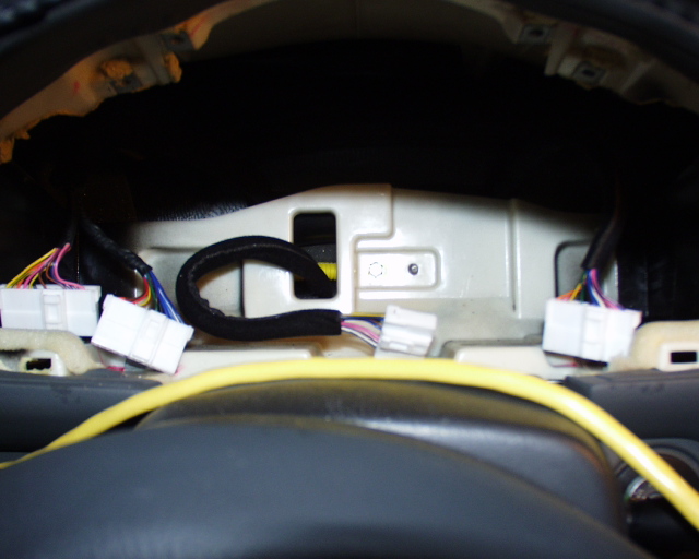
With the
cluster partially taken out you can see the wire harnesses. Just unplug
them, they pop off actually pretty easy by pressing the little tabs.
Gently pull towards you the glove box to detach
it from the area.
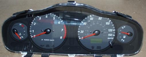
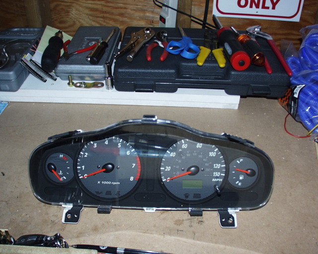
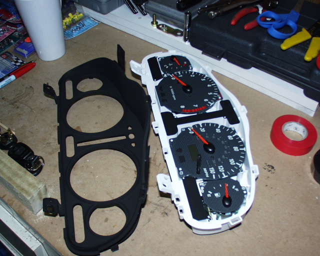
The gauges
stay in place and are from left to right, the temp gauge, tachometer,
speedometer and fuel gauge.
Don't worry about mixing them up, they should stay in position where you lay
them. Plus they are of different sizes and can only go into the cluster in
each owns slot.
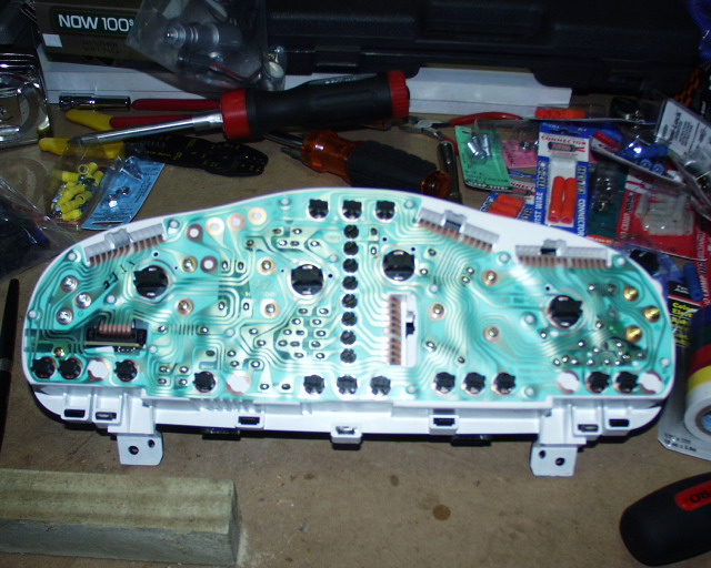
The
instrument panel should be out of your Santa Fe and be ready to be worked
on. Take it to a well lit area. This pic shows the back part of it.
Once the
cluster is in a well lit area you can now perform the steps in
modifying it with the new gauges.
Step 2:
Dismantling the Instrument Cluster.
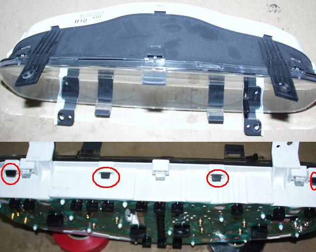
The cluster
has two outer pieces that need to be removed. First remove the plastic front
clear housing. All of the the plastic trim is held on by clips, which can be
removed by pushing down and pulling apart the pieces.
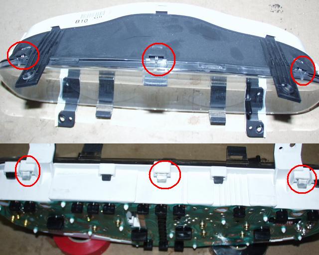
There are three tabs on the top of the cluster and three on the bottom. Do
not force it and risk cracking or scratching the plastic.
Put the
plastic clear cover to a safe area.
Do the same
thing for the black plastic inner overlay. See pic for location of tabs.
Gently remove the overlay.
Place the
overlay in a safe area away from your work table.
At this point you may choose to paint the black plastic panel a different
contrasting color, I choose not too.
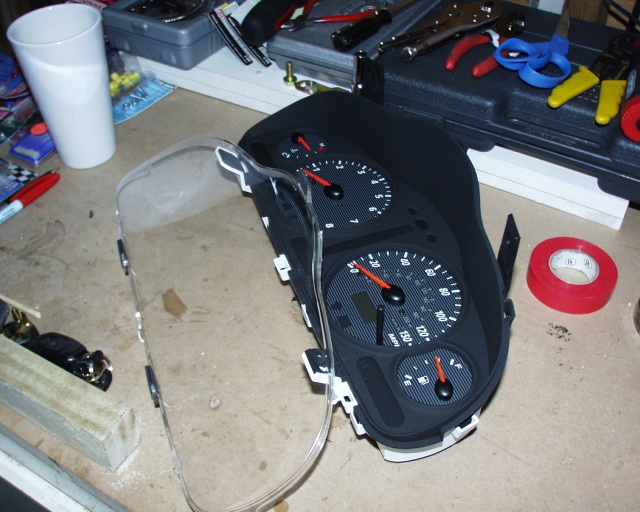
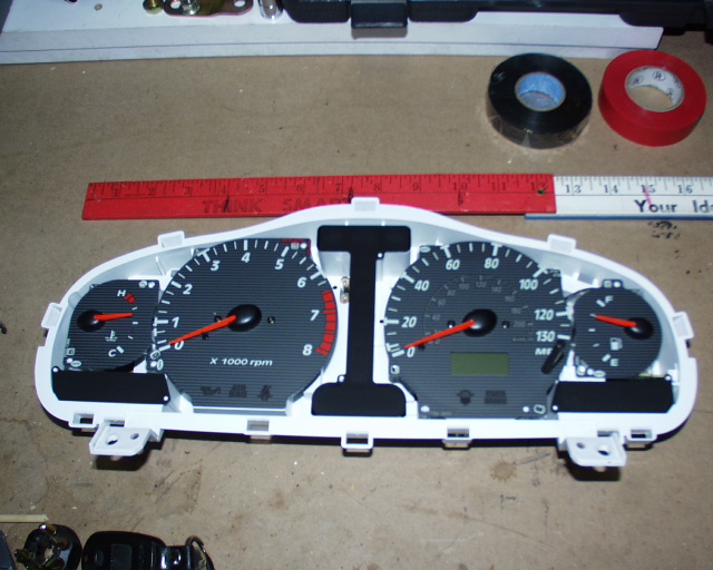
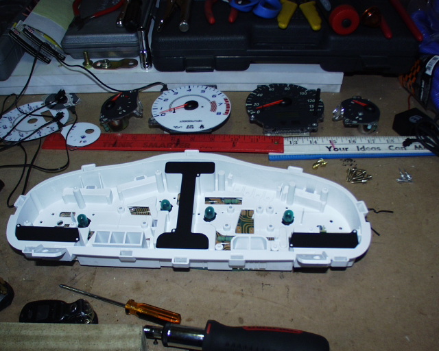
This is what
the cluster should look like with only the stock gauges attached. You can
see that only the tachometer and speedometer gauges have screws in them from
the front. All the gauges are attached to the cluster with screws in the
rear of the cluster.
At this point the modification can proceed in either of two ways. 1-by
attaching the new gauges without taking the stock gauges out of the cluster.
or 2-by taking out the stock gauges out of the cluster. I decided to take
them out of the cluster to prevent the circuit board backing from being
scratch or damage.
Step 3:
Adding the new gauges. (individually out of the cluster )
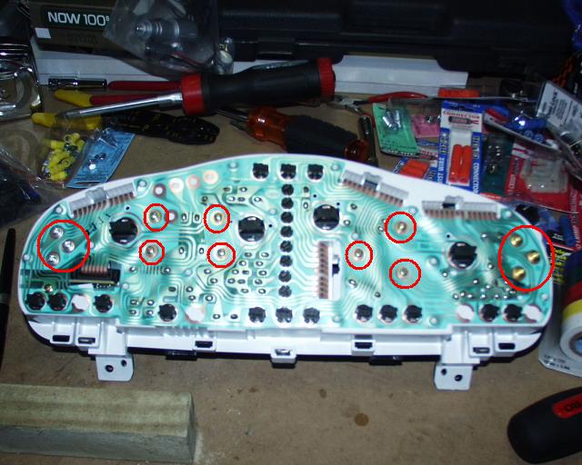
Turn the
cluster around to its back side and take out the screws that hold the
gauges.
This allows
you to work on the gauges individually without scratching or harming the
circuit board back side. With the gauges removed from the circuit board
backing/cluster we can now work on the gauges. Lets start with the
tachometer.
Remove the screws (4 total) around from the tachometer and speedometer,
with a #1 or # 0 Philips head screwdriver.
Do not use a larger
screwdriver or you will end up scratching the screws.
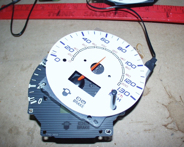
With the
tachometer and speedometer you will notice each has a small stop pin that
holds the needles from unwinding. Removal of the needle is not needed, and
basically impossible. therefore you need to place the new gauge through and
over the needle. While the new gauge had a round hole you will notice that
the center bulb is oval.
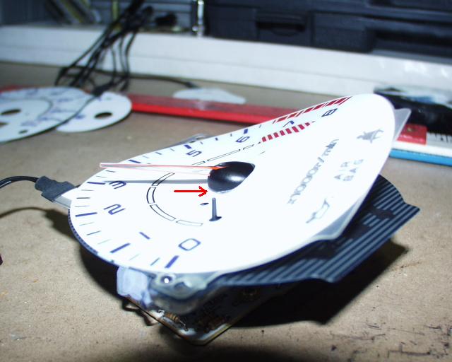
For the
tachometer insert the new gauge over the needle but position it so that the
stop pin goes through its appropriate hole. Move the needle away from the
stop pin to get the right angle and put it through the hole. Position the
gauge under the front part of the bulb.
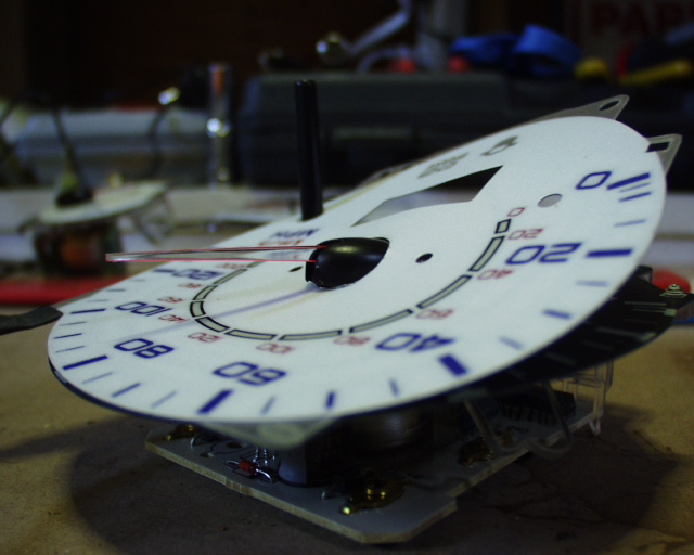
When sliding
the gauge face push down so the gauge face goes as far as possible under the
front of the center of the bulb first, this allows you to be able to get the
rear part of the gauge over the bulb, continue and pull along the narrower
sides of the needle bulb. I'll be much easier to push over the bulb if you
pull it under the front first. Once it pops into place all should be fine.
This will be a bit hair-raising, but it will be easier if you do it this
way.
Once the new gauge is on the old one and in place, you need to make a
decision. Some members have noticed that some of the original light from the
cluster may seep/leak through the edges and create an eerie type of glow.
You can at this point spray paint the back sides or laboriously cut and fit
electrical tape over the backs. I did the tape procedure. Of course you can
also leave them as is and skip it.
See Appendix A
below for the procedure.
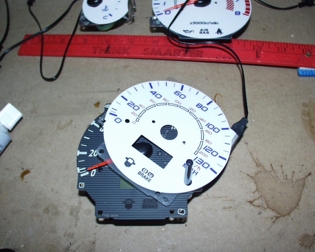
Next to be
done is the Speedometer. Insert the new gauge over the odometer reset post
then slide the gauge to the right.
By sliding
the gauge to the right you can now move the needle also to the right to
allow it to go through the gauge hole.
Perform the
same procedure as you did with the tachometer by sliding the gauge under the
bulb first then then slide the rear of the gauge over it until it pops into
place.
At
this point you may want to perform the 2 steps shown in Appendix A below to
prevent the gauge from leaking light around the edges. Or you can leave them
as is.
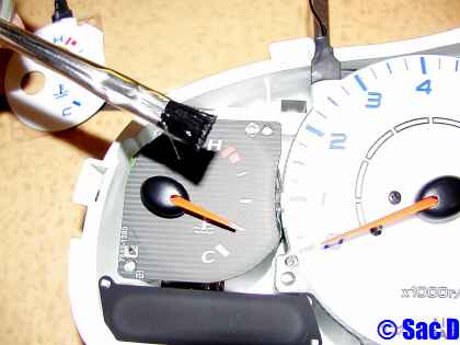
Now do the
Temperature and Fuel gauges. Some members have had problems with these two
gauges because they are not held down by tiny screws like the Tach and
Speedo ones. But I left them in place instead of cutting them out and used
an adhesive like rubber cement or superglue.
As before you may want to do
the steps mentioned in Appendix A below to prevent the gauges from leaking
light around the edges, otherwise leave as is.
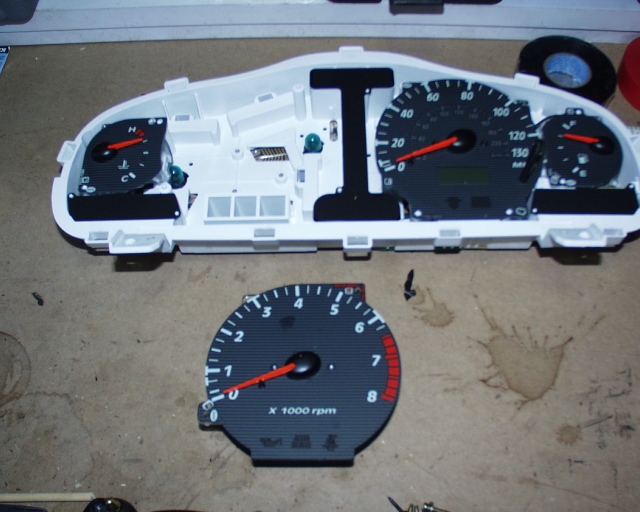
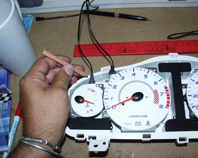
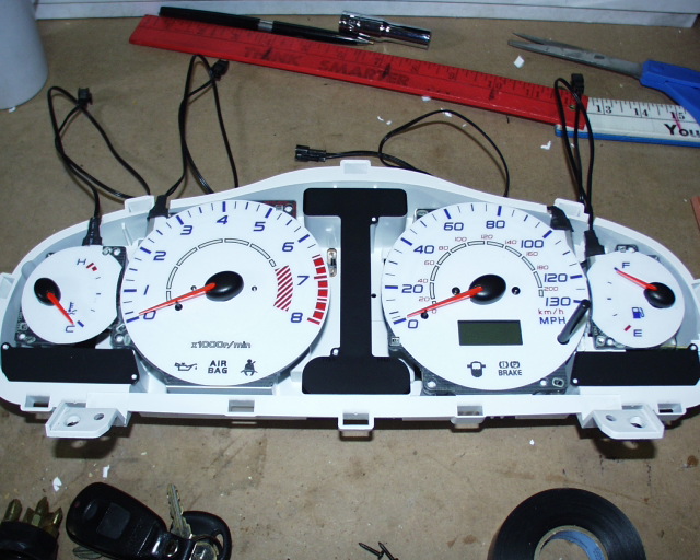
The new
gauges should all be done at this point as shown here. Place the gauges back
onto the circuit board cluster but do not screw them in yet.
Step 4:
Fitting the wires in the cluster.
The wires
will fit fine in between the black trim and the cluster, but to me it felt a
bit in the way, therefore you might want to use an Exacto knife to cut a
groove for them.
With the gauges placed in their positions on the cluster (but not screwed
in) take a pencil and mark where the wires are crossing over the edge of the
cluster. Remove the gauges from the cluster and cut the cluster at the marks
to make the grooves.
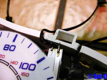
Place the
gauges back to test if the groove is big enough for the wires to go through
without any problem.
It should
look like this close-up of the groove.
After all the
groove are deep enough, place the gauges back and screw them into place onto
the cluster.
Place the
black cluster cover back on and check to see that it is firmly snaps into
place.
Place the Clear cover onto it as well, make sure it also snaps into place.
Make sure that the the black cover and the clear cover are free of
fingerprints and dirt/dust. Once the items are together and working any
little smudge will show with more intensity.
The gauges
are now done. Before we proceed with the next set of instructions this is
what the kit looks like.
The four EZ-Connectors for each gauge, the transformer, the dimmer rheostat,
the blue/green toggle switch and the power ground leads.
Step 5:
Placing and wiring the gauges.
Now you are
ready to get everything hooked up. The easiest place to put the starter
(control) module so it is out of the way and to be able to hook up the power
and ground leads was behind the dash light rheostat panel.
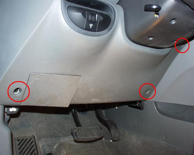
Therefore the panel below the
steering wheel that holds the rheostat has to be removed. There are three
screws and clips that hold it in place. Remove these screws.
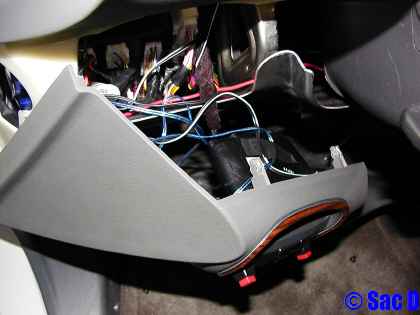
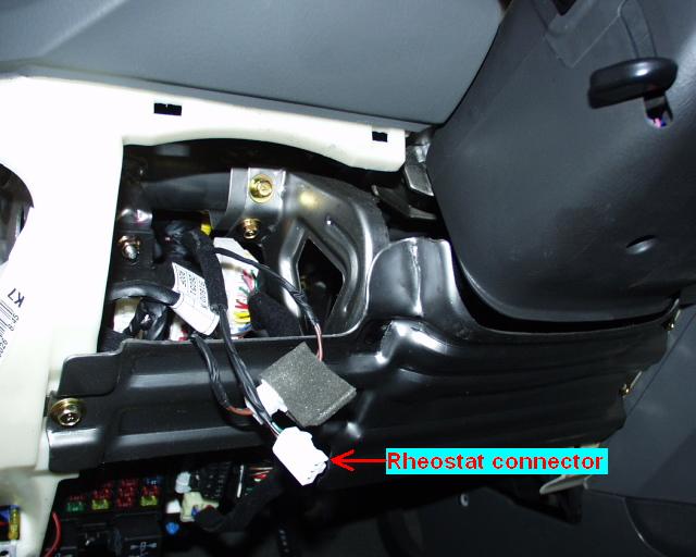
Now remove
the panel put your fingers in the rheostat opening and push down slightly
while pulling towards you and it will pop out into your hands. As you can
see the wires attached to the rheostat module are not that long.
Unclip the
connector from the back of the rheostat and the panel will be freed.
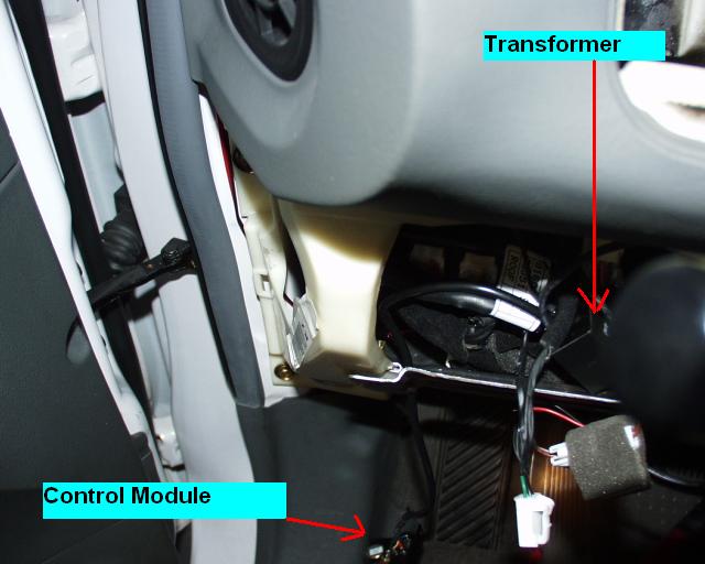
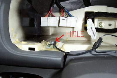
Route the
transformer and its wires from below to the area behind the rheostat wires.
Route the
power pin wires (the ones that connect to the gauges) up and through the
upper left side of the hole opening to get the wire into the instrument
gauges area.
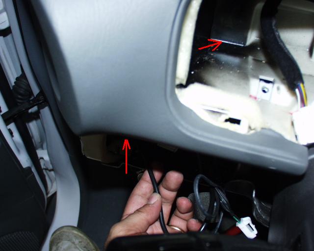
Place double
side (3M) tape and place it on the transformer.
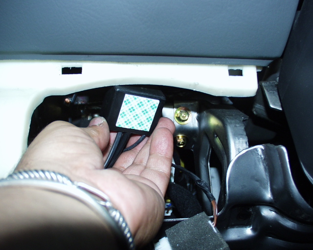
Remove the
other tape cover and place the transformer inside the upper part of the
area. (Make sure you clean the inside area first with alcohol or the
transformer will not stick to it.) This prevents the transformer to be
moving back and forth and make hitting noises while the vehicle is in
motion.
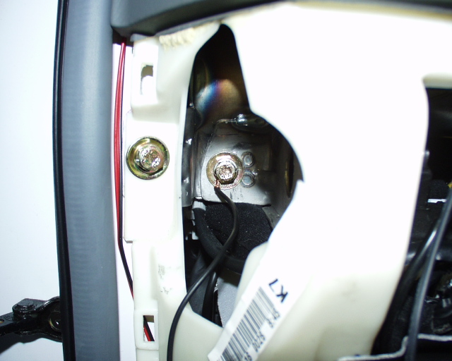
Take about
6-12 inches of black 18 gauge wire and attach it to the copper nut bolt
that's located in the small left side opening. Feed this wire through the
hole to reach the rheostat area. This will be your ground wire.
Or you can
attach the ground wire here like member Oni did by grounding it to the
cluster bolt.
The kit has
two wires to hook up. A black (ground) wire and a red wire. Now we hook up
the power / ground to the starter (control) module first.
Remove the electrical tape
surrounding the rheostat wires.
Taking a Posi-Twist connector we connect the two black wires together (the
one coming from the starter and the one that you just attached to the
grounding bolt.
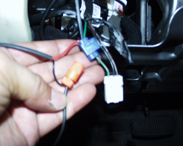
Being that we
only want the Indiglo Gauges to come on only when the lights are turned on
we need to attached the kits red (positive) wire to the rheostats green with
orange stripe wire (positive). You can use a Telephone Wire Tap Connector (
from Radio Shack) or like what I did. I added an an additional red color 18
gauge wire that I connect to the kits red wire using a Posi-Twist connector.
Then I connect the end of that wire to the rheostats' green with
orange stripe wire with a blue butt connector. This allows me to have ample
length of wire to work with and secure the wires together since the kits
wires are quite thin.
Connect the
lead wires to the gauges and test the system to see if they light up. if
everything is working fine then you can proceed to the next set of steps to
place the control module in a secure area within the cabin.
Step6 : Placing the control
module.
After checking if the system works, you will need to select where to place
the control module and color select switch. You can do any of the following
methods...
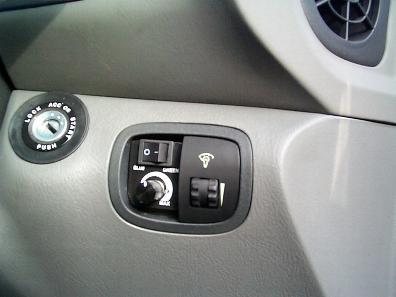
Method Placement 1
This method
performed by SFF member Sac D.
Cut
a piece out of the gray plastic to fit the area to the right of the original
dash rheostat and mount the Indiglo switch and rheostat there. If you do
this, you will have to unsolder the color selector switch to be able to
un-mount it off of the original bracket and mount it elsewhere. Use a little
RTV (silicone) to keep the starter (control) module from moving around where
you wedged it between the dash and the support bracket. RTV is easy to
un-mount if you ever need to do so. OR,
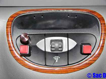
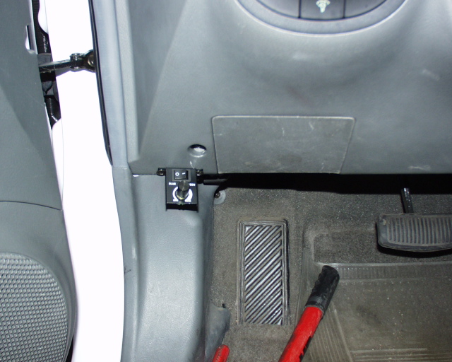
Method Placement 2
This method
performed by SFF member twospirits.
Leave the starter (control) module and color selector switch intact (as is)
and just place it on the lower part of the rheostat panel. This allows you
to select the color at any time you want (depending on your mood) and have
easy access to it to turn it off if need be.
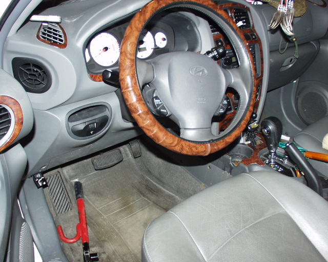
Method Placement 3
This method
performed by SFF member HardyDoug.
You can also place the switch where the rheostat is near the steering
column.
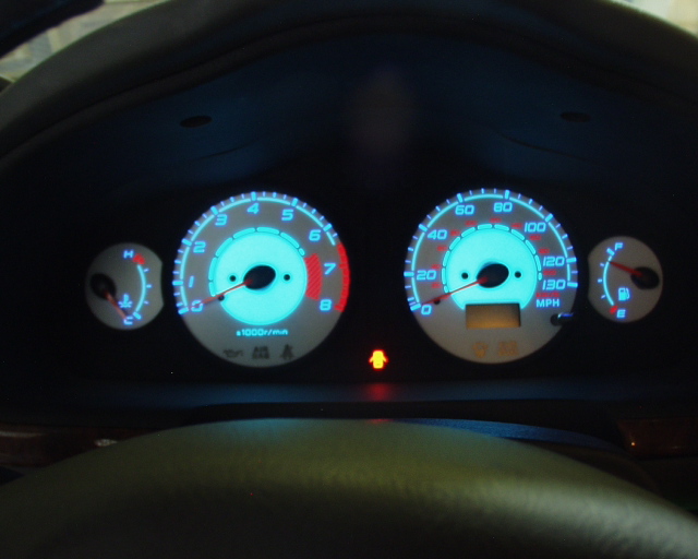
Turn on the
vehicle. Adjust the instrument panel backlights and the Indiglo gauges light
intensity. Select your Indiglo color of green or blue. Rev it up. Does the
RPM needle move? Does the Fuel register? The same for the Temp gauge.
If so then reattach the cluster back into the dashboard and go out for a
test spin. Check to see if all the gauges work as they should and not stick
and that nothing rattles.
Now enjoy your new Indiglo Gauges.
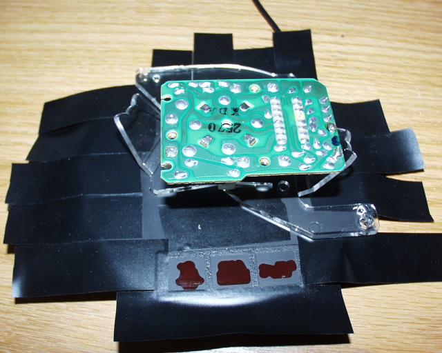
Appendix A : Quick fix to prevent the gauges from
leaking light at the edges.
Some members have noticed that some of the original light from the cluster
may seep/leak through the edges and create an eerie type of glow. You can at
this point spray paint the back sides or laboriously cut and fit electrical
tape over the backs. I did the tape procedure.
Cut electrical tape and
place it on the back of the gauge.
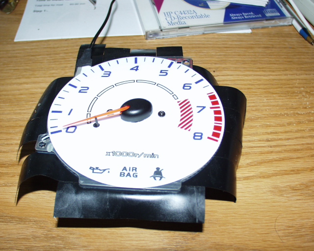
Make sure
that you cover as much of the back as you can. This is what the front of it
should look like this now.
Take a small
scissor or an Exacto knife and cut as close to the edges of the gauge as
possible with about 1/16th of an inch overhang. Now place the gauge back
into the cluster.