Hyundai Santa Fe DRL Installation
(Daytime Running Lights)
Installer:
twospirits, Roland
Testers:
twospirits, Roland
Part supplier:
GNU Industries, Sunrise
Florida
Author, Images:
twospirits, nsdy2K
Technical assistant:
southpawboston
Introduction
/ History
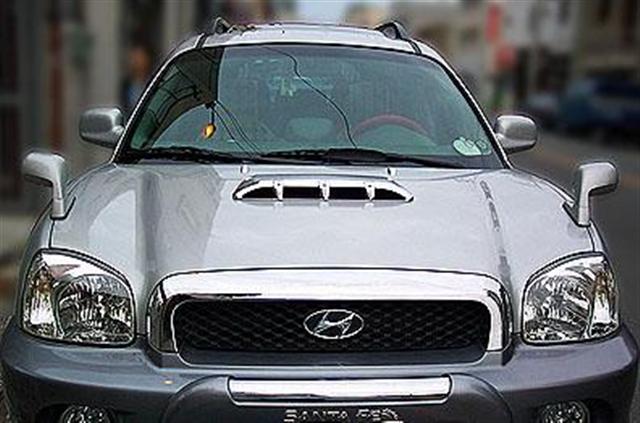
The
Hyundai Santa Fe's sold throughout Europe as well as in Canada come with
Daylight Running Lights. These lights greatly improve the visibility of a
vehicle when a vehicle is viewed from the front in daylight by oncoming
drivers and reduce your chances of being in an accident compared to if you
did not have them. Studies have shown that driving with headlights during
daylight hours will reduce your chances of being involved in an accident.
Numerous studies have been conducted in the US, Canada, England etc and have
shown a positive reduction in daytime accidents by up to 38%. In addition
the U.S. Insurance Institute for Highway Safety also conducted it owns study
which indicates a 20% reduction in daytime accidents. Unfortunately the US
models do not come with the DRL unit installed. It is up to the owner to
obtain an aftermarket module that will give the Santa Fe this extra safety
enhancement. Its a safety enhancement because DRLs can cut your accident
rate by 10-30% in the first year of installation. In addition most
automobile insurance companies will re-evaluate your insurance premiums when
DRLs are installed on your vehicle. In 99% of cases the insurance company
will automatically give you a premium discount. That alone offsets the cost
of the DRL unit. Once you complete the modification/installation you can
send a copy of your sales receipt to the your insurance company and get the
DRL discount.
This modification therefore tackles this problem by guiding you in
installing an aftermarket Daylight Running Light module.
Acknowledgement: Special thanks go out to SFF/ElantraGT Club member
southpawboston which without his expertise this mod/install would not have been
possible, as well as to Roland/nsdy2K
for additional photos and notes in Appendix B.
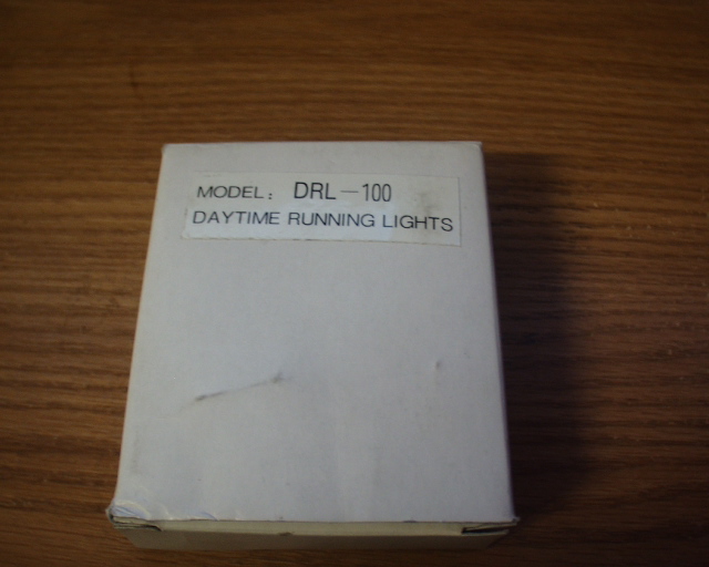
GNU Daylight Running light module DRL-100
(see above)
Philips screwdriver
10mm Socket wrench with extension
2 Blue Butt Connector
Electrical tape
Optional
Isopropyl Alcohol
4-6" of 18 gauge electrical wire (any
color)
Clean Rag
1 or 2 nylon snap ties
Heavy duty double sided tape
1 10 amp "Add a fuse" from any Auto parts
store
Time to install item:
Total time for mod:
30-90
min
Necessary
pre-mod/install steps.
Before any modification / installation, write down
any pre-set radio stations you have set your radio too.
Then disconnect the battery.
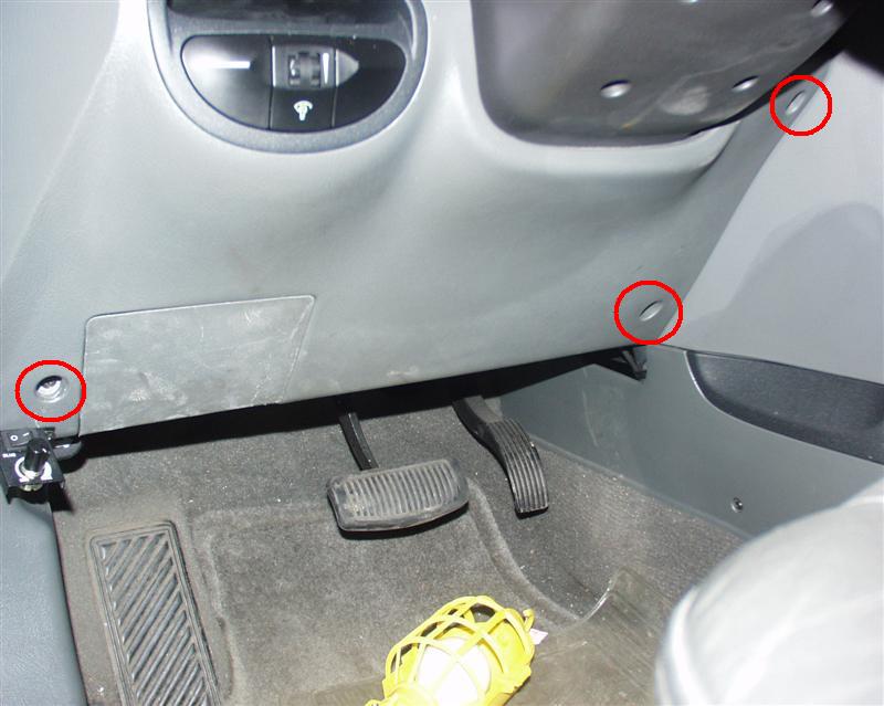
Removing the
necessary panel covers.
Place the drivers side seat as far back as possible.
Raise the steering wheel to it up most position.
Remove the 3 screws from the left lower crash pad panel.
Gently but firmly unclip the crash pad
panel by pulling it towards you.
Be careful as the Rheostat M11 switch will still be connected to the
Rheostat and you will need to unplug it during the panel removal.
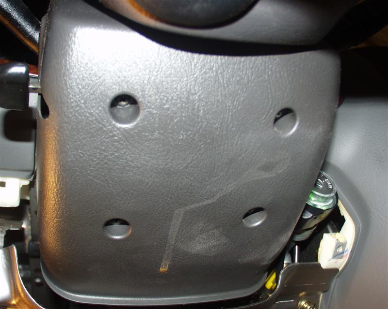
Remove the 4
screws from the underside of the steering column cover.
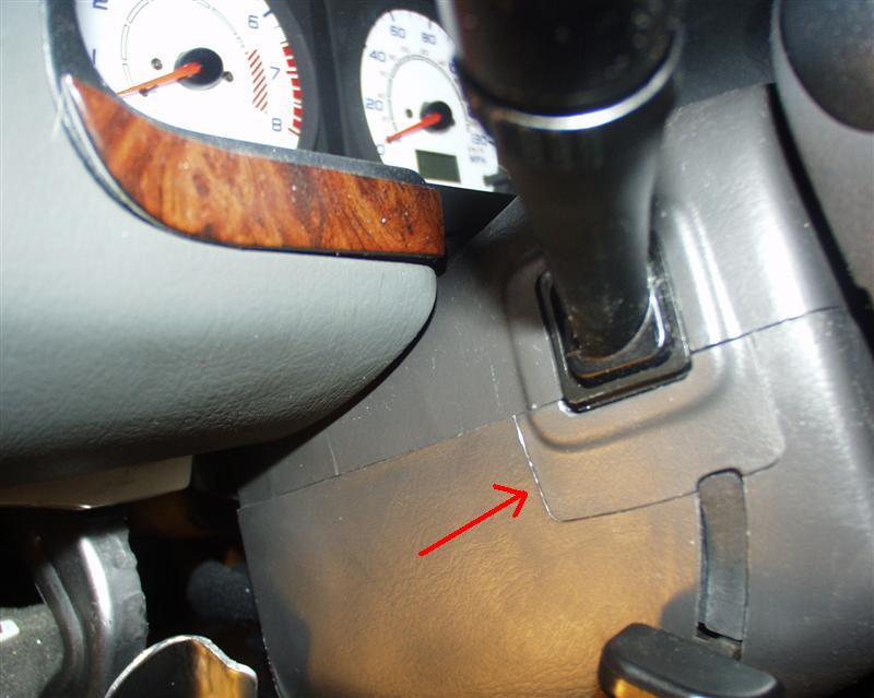
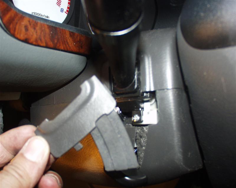
The steering column cover has a small enclosed cover that you need to pry
open either by using a flathead screwdriver or a door trim tool or any tool
that you find that will not scratch the cover.
The small
enclosed cover shown removed with the rubber attachment.
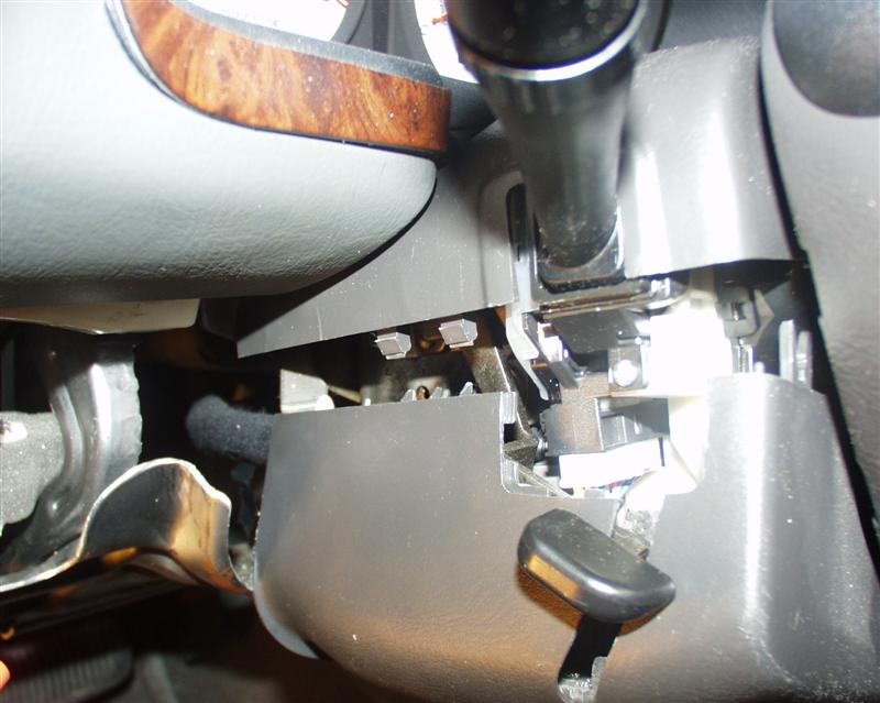
With the
enclosed cover removed you can insert your fingers to separate the upper and
lower steering wheel cover.
Gently but
firmly grasp the lower cover and pull downward and the covers will separate.
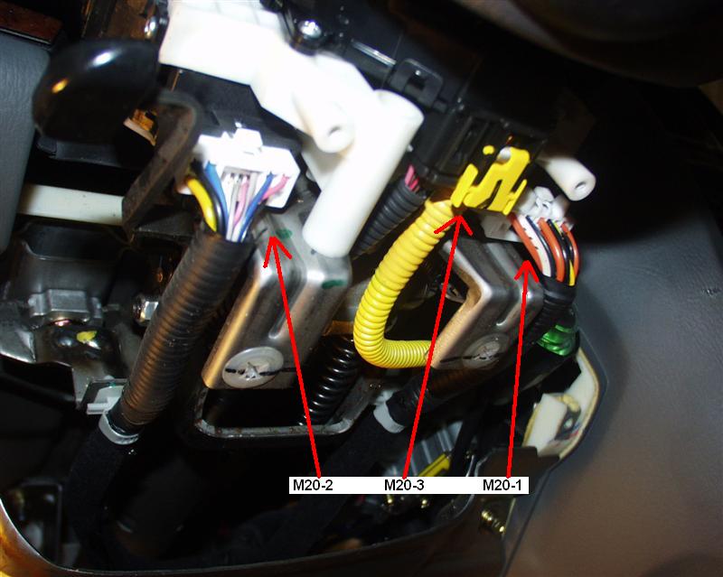
With the
steering wheel covers removed you will see and have access to the
multifunction switch connectors M20-1, M20-2 and M20-3.
Detach the
M20-2 connector so it hangs. Unwrap the electrical tape and take out the
wires from the protective plastic hose.
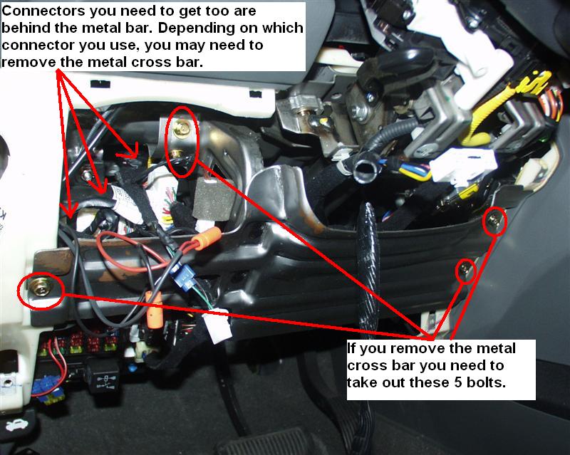
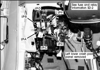
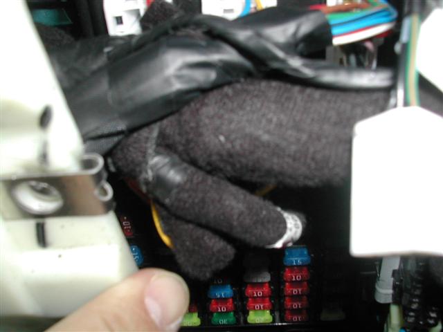
The Passenger
fuse box connectors are located behind the lower metal crossbar. Depending
on the connector you plan on using depends on you removing this cross bar. I
would suggest to remove it anyway for better access. To remove the lower
metal cross bar you need to remove the 5 bolts shown in the picture with a
10mm socket. For the two inner bolts you will need to use a socket extender.
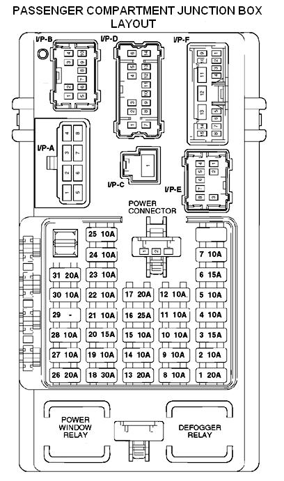
Determining which
connector to use depending on the model you have.
In
a real world the best connector to hook up the DRL module would be to the
I/P-A connector at Pin #2 (the red wire). But due to the placement of the
Passenger Compartment Junction Box, (see picture left) it will be next to
impossible to get to this connector. Therefore I suggest hooking up the DRL
module to the connector I/P-D which is higher and a bit to the right (see
diagram) and easier to unclip than any of the other ones. Tester
Roland/nsdy2K actually did connect the wires to I/P-A (see Appendix B below
for instructions and photos.)
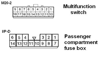
Now using this connector you have the option of hooking the DRl to any one
of the following pins/wires from Connector I/P-D.
Stop
lamp switch, data link connector, multipurpose check connector
Green, Red
#
15
10A
Hazard
lamp
Red
#
16
25A
Rear
wiper motor control, power seat
Red
#
17
20A
Sunroof
relay
Green
#
18
30A
Rear
window defogger
Red
#
19
10A
Pre-excitation
resistor, instrument cluster, ETACS control module
Orange
#
20
15A
SRS
control module
Red/Black
#
21
10A
ECM
(V6), PCS (I4 with A/T), ECM (I4 with M/T)
Red
#
22
10A
Instrument
cluster (Air Bag IND)
Blue/Orange
#
23
10A
G-Sensor,
ABS control module, air bleeding connector
Blue/Orange, Red/Orange
#
24
10A
Turn
Signal lamp
Red/Orange
#
25
10A
Back
up lamps, vehicle speed sensor, TCM
Red/Orange
#
26
20A
Door
lock//unlock relay
(internal)
#
27
10A
Turn
signal lamp, License lamp, Tail & Parking lamp (LH)
Brown/Orange, Yellow, Pink
#
28
10A
Fog
lamp relay, switch illumination, Tail & Parking lamp (RH)
Pink.Black, Yellow,
#
29
-
(Not
Used)
#
30
10A
Radiator
fan relay, condenser fan relay
Green
#
31
20A
Front
wiper motor, wiper relay, washer motor
Red
Note: Once you unclip this connector you will see the available wires
leading off of it. I suggest hooking up the DRL to Pin # 2 (white wire that
leads to the Electronic Chrome Mirror). Some models have the Electrical
Chrome mirror and or sunroof, if yours does not, then I suggest hooking up
the DRL to Pin # 14 (yellow wire) that leads to the Vanity cabin lamps.
This diagram shows the M20-2 and I/P-D connector and their associated pin
placement.
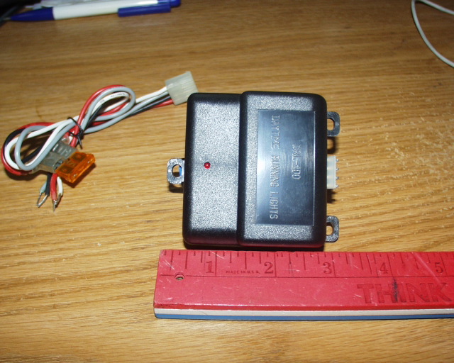
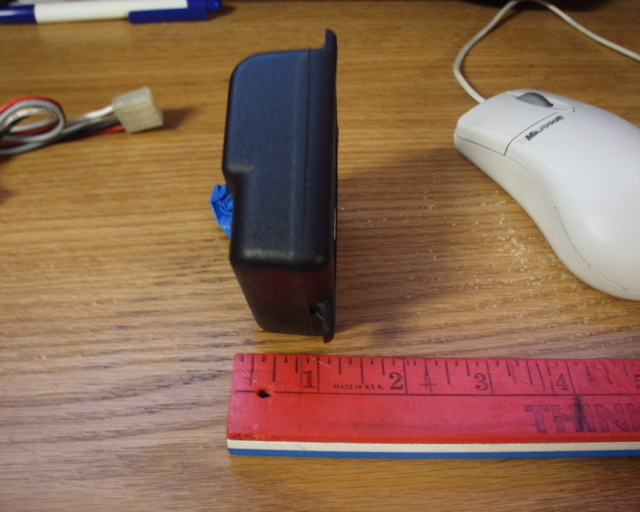
Familiarizing
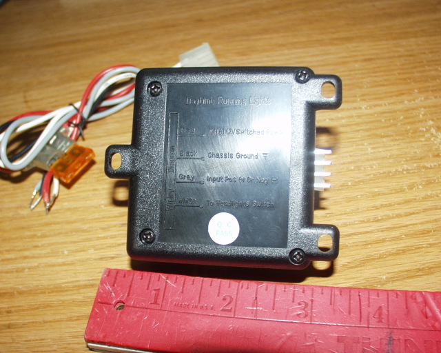
yourself with the The Daylight Running Module (DRL).
The DRL module is quite small with instructions on the back of the unit.
While these instructions may be used generically for other vehicles they are
NOT to be used for the Santa Fe.
The instructions shown on the back of the unit are as follows....
Unit Wire
connects to
Red wire
=
Ignition (+) 12V switched power
Black wire
=
Chassis ground
Grey wire
=
Input Positive (+ ) or Negative (-)
White wire
=
To headlights switch
As mentioned, with these instructions the unit will not work with the Santa
Fe. Therefore with assistance from fellow electronic guru southpawboston, he
was able to come up with the right connection as follows...
Unit Wire
connects to
Red wire
=
Passenger fuse box connector I/P-D Pin 2 red wire or Pin # 14 (depending on
model)
Black wire
=
Chassis ground
Grey wire
=
Chassis ground
White wire
=
Multifunction control M20-2 Pin 10 Yellow wire (low beam) or Pin 2 Blue wire
(high beam)
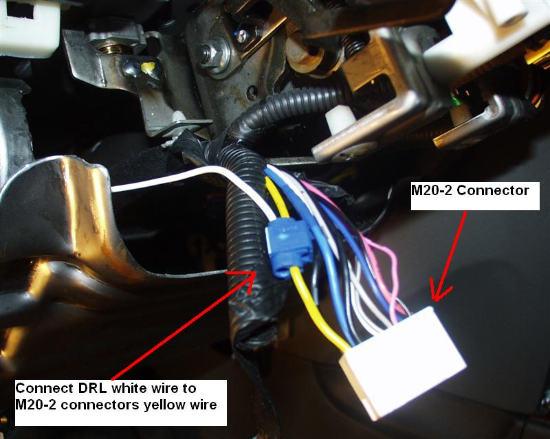
Connecting the
Daylight Running Module (DRL).
Connect the DRL white wire to the M20-2 Connector using one blue butt
connector (or solder it or any connector you prefer).
To
connect to the low beam lamps.
To connect to the high beam lamps.
Connect the DRL white wire to the M20-2 connectors yellow wire.
Connect the DRL white wire to the M20-2 connectors blue wire.
Note: If
connecting to the high beams please see Appendix A below for special
notations.
I
added one 10 amp "Add a fuse" which I obtained from AutoZone to the
white wire. This will give more protection in the event of any additional
load being sent to the module.
Connect the DRL red wire to the I/P-D connector using one blue butt
connector (or solder it or any connector you prefer).
Connect according to your models factory installed item.
models with Chrome mirror.
models without chrome mirror
Connect the
DRL red wire to the I/P-D connector white wire (pin # 2)
Connect the
DRL red wire to the I/P-D connector yellow wire (Pin # 14).
The red wire already has a fuse to it, but as mentioned above I added an
additional one to the white wire for added protection.
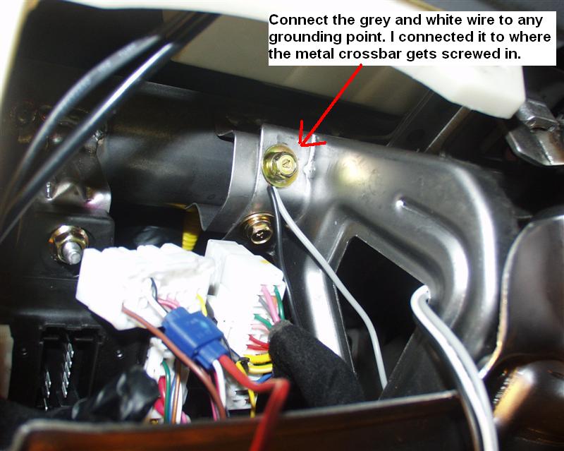
Connect the DRL grey and black wire to any chassis grounding point.
I chose to connect it to the inner most bolt where the metal crossbar gets
attached too.
Testing the DRL.
At this point, reattached the battery and
test the DRL setup by having the vehicle turned on and see if the lights come on
and the led on the module is on as well. If it does, it works. If it does not,
recheck the connections.
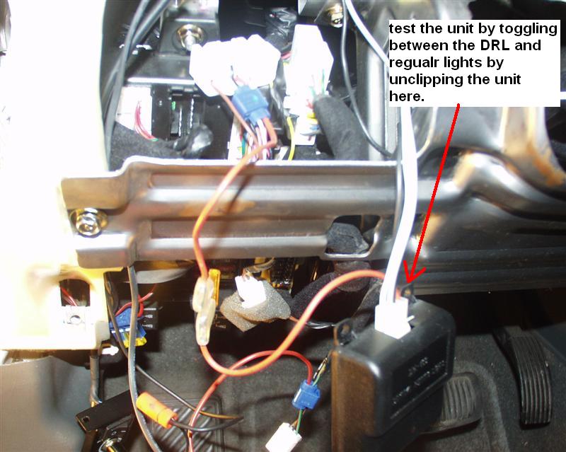
You can test the lights by toggling between the DRL and standard lights by
unclipping the module. You should be able to see a light intensity
difference if the lights are towards a dark wall such a garage wall or
building.
Securing the DRL
module.
At
this point, knowing that the DRL works, you can wrap up the project by
securing the loose wires by wrapping them up in electrical tape as shown.
This is the M20-2 Connector plugged back in.
Securing the DRL
module.
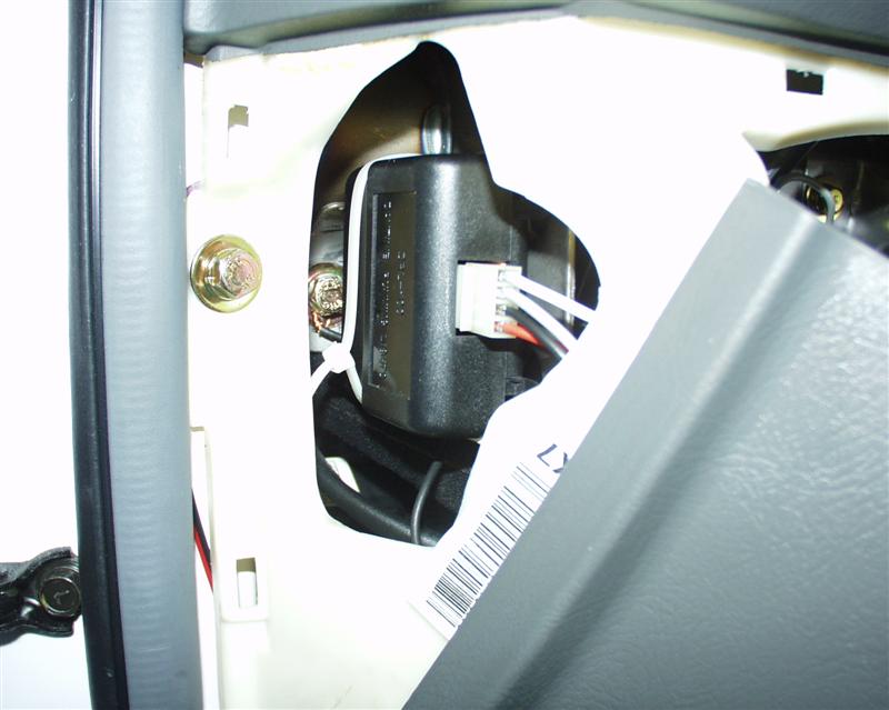
Placement and securing the DRL module is a bit tricky since the most logical
place would be in the space above the passenger fuse box.
But placing it here will be a problem
because it gets in the way of the rheostat once the lower crash pad is put
back in place.
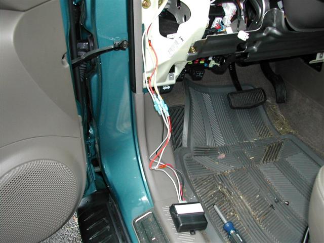
Therefore I place the DRL unit in the nook to the left of the lower crash
pad. Unfortunately the DRL red wire is not long enough, so you will need to
cut it in half and add about 4-6 inches of additional wire to it so it can
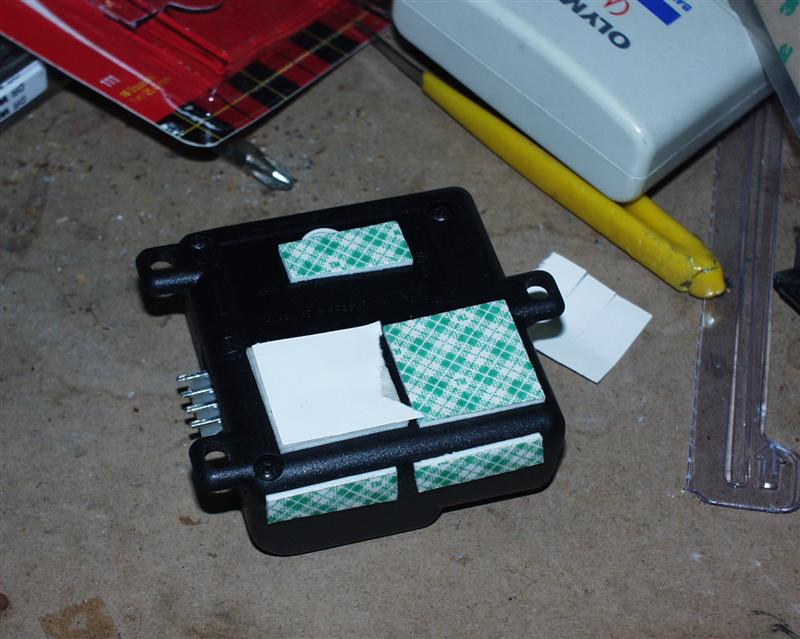
stretch far enough to be placed within the nook. Clean the metal inside the
nook with a clean rag dabbed with alcohol. Add double sided tape to the
module.
Place the DRL in the nook, and against the metal. If need be, hold it down
with a nylon snap tie in the event the tape does not hold.
Final wrap up.
At this point, knowing that the DRL works,
and is secured, you can wrap up the project by putting back the lower crash pad
and steering wheel covers in reverse order as mentioned above in the section
"Removing the necessary Panel Covers". Re-connect the battery and reset your
radio setting.
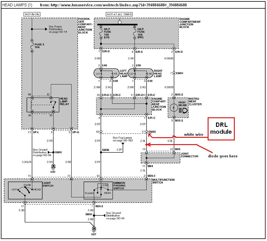
Appendix A.
If you plan on connecting the DRL modules
using the high beam lamps you need to know that the high beam indicator in the
instrument panel cluster will be on at a dim level. To overcome this you will
need to isolate it with a blocking diode by hooking up the DRL white wire to
EM03 pin # 17 (which is downstream of the multifunction switch). Then insert the
diode inline between joint connector M04 pin 13 and EM03 pin # 17. This will
isolate the dash indicator from the DRL module but allow the indicator to work
normally when you switch on the high beams.
Appendix B (using
the I/P-A connector instead of I/P-D).
The following guide was performed and
provided by Roland / nsdy2K.
I study your DRL 4-wires
descriptions and followed the wiring diagram on Appendix A. I concluded for
safety measure that the +12V power source must come from I/P-A pin#2 or
somewhere similar which can provide capable current draw in case the DRL
module need to sustain it. Also since the SF headlights are negatively
sourced, the grounding wires (gray & black) of the DRL are extremely
important because they will be handling the full current load for the
daytime headlights.
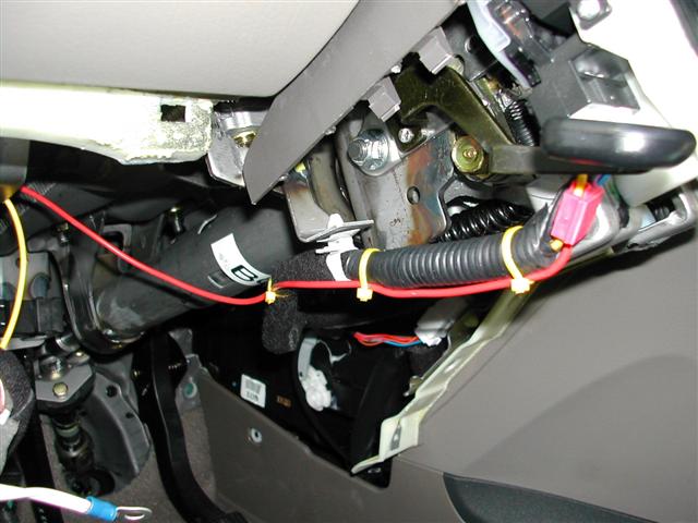
In summary I ran separate wires for each connection and terminated them with
a quick disconnects. All the wires pulled to one location where the DRL will
be installed.
I used 18 AWG and splicing
connector on connector M20-2 Pin# 10 (yel). Tie-wrap the line to existing
harness and run neatly underneath to left side of dash.
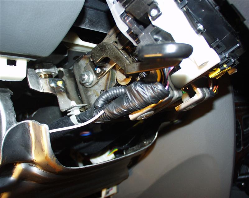
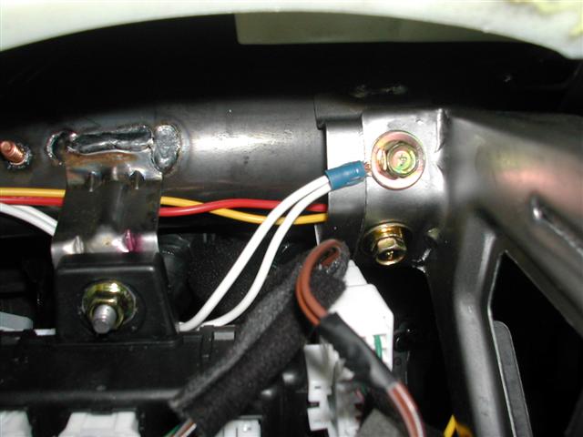
Crimp (2) 16 AWG wires to 16-14 AWG ring terminal (eyelet
connector). This will be used as the grounds for the DRL on the headlights.
This ring terminal will be bolted to the cross-bar using the
existing hole and bolt.
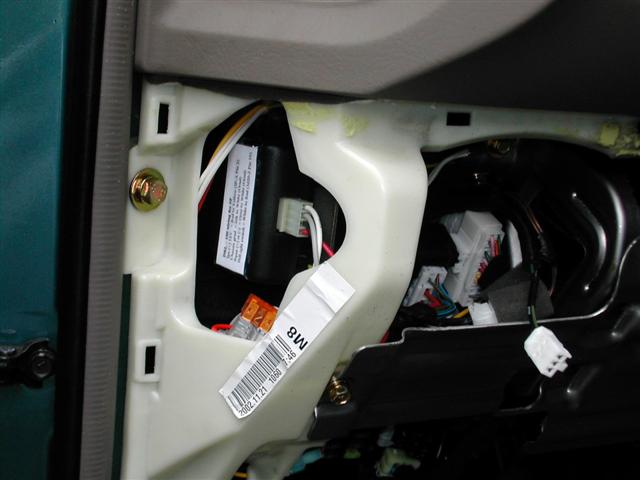
I was able to access the
connector I/P-A after unclipping the top connectors and pushing the harness
up slightly. You need to press the side lock in and hold it flush to the
side of the connector and pull it straight out. There is not a lot of play
in the lock, don’t press too hard otherwise it will bend the tab and clip
more on the lip. Just hold it in firmly.
You can see the 16 AWG
yellow lead from the splice on connector I/P-A Pin# 2 (red).
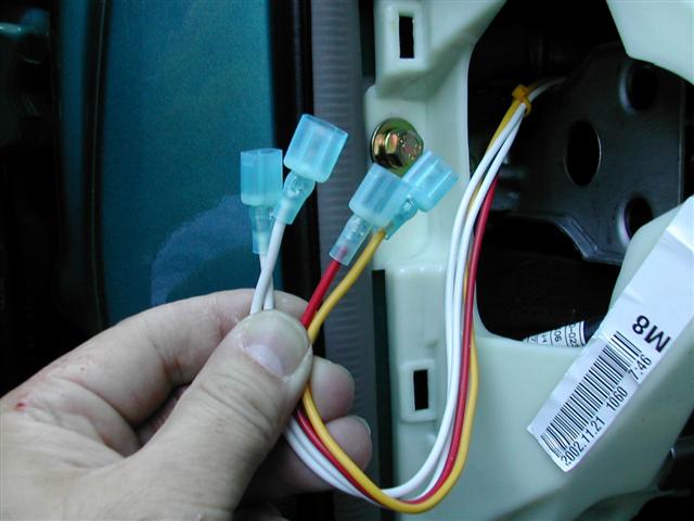
I brought all the wires over to the left side.
Terminated them with quick disconnects as shown.
Again I used 16 AWG for all grounds & for +12V hot source. Ran 18 AWG for
the HL trigger lead.
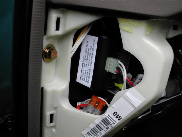
I made a lable and taped it to the DRL front
cover.
DRL – 100 wiring for SF Ign (+) 12V = Red to Yellow (IP-A
Pin 2)
Chassis grnd = Blk to White (Grnd)
Input (+) or (-) = Grey to White (Grnd)
HdLight switch = White to Red (M20-2 Pin 10)
I added quick disconnects (female) to each ends
of the power cable from the DRL.
Before putting the panel back, I tested the DRL. I started
the car and waited 5-6 seconds for the module to activate; the DRL led came
on after 5-6 seconds delay. The DRL is designed to delay 5-6 seconds for
normal ignition start. The headlight is designed to run at reduced-intensity
(I don’t know the exact percentage, but others DRL advertised at 60%).
Ties wrap the DRL to the frame and retest it.
After tests, I plugged the rheostat
connector to the panel and screw the panel back. Tested again and the dash
light is bright and the DRL is working properly.