The Hyundai Santa Fe Alarm LED Scanner Modification
| Original idea: | markoz74 |
| Author of procedures: | markoz74, twospirits |
| Installer / Testers: | markoz74 |
| Parts Supplier: | ebay |
| Images provided by: | markoz74, MetalMessiah, twospirits |
Introduction / History
| In place of a flashing bulb as shown in the Alarm LED modification on e can use a LED Scanner that provides a scanning light effect when arming the vehicles' security system. |
|
Disclaimer
|
Difficulty level / scale: On a scale of 1 - 10
| Easy | Difficult |
| 1 | 2 | 3 | 4 | 5 | 6 | 7 | 8 | 9 | 10 |
| X |
Tools and materials needed:
| 1 RedLine LED Scanner Light (can be found on ebay or some Auto parts store) |
| Long nose pliers |
| Drill |
| Optional: |
| Electrical tape |
| Wire (to extend the Scanners existing wire) |
Step 1: Obtain the Scanner.
(Click on images to open up in
full size)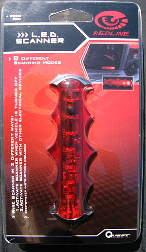 |
The Redline LED Scanner can
be obtained on some auto parts store as well as on
ebay. |
|
|
|
|
|
The effect is similar to the effect that is shown on the futuristic KITT car on the 70's Knight Rider television series. |
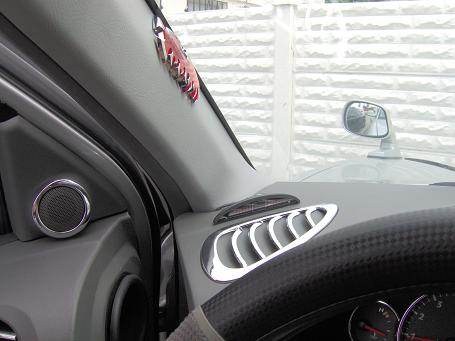
Step 2: Placement of the LED scanner.
(Click on image to open up in full size)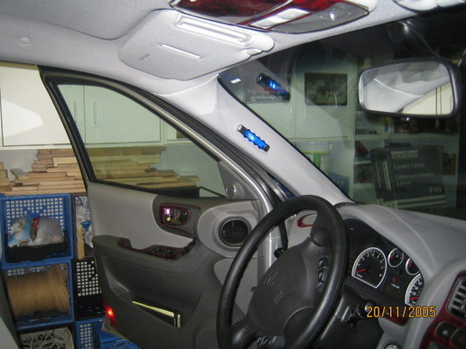 |
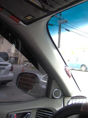
The Redline LED Scanner is approx 4 inches long by 2 inches high and is small enough to be placed anywhere within view from the outside. One possible placement is on the drivers side A Pillar. The Redline LED Scanner has
3 cables: a RED, a YELLOW and a BLACK. |
(Click on image to open up in full size)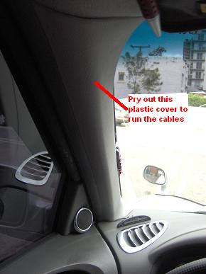 |
Gently pry out the plastic cover on the drives side A pillar. |
(Click on image to open up in full size)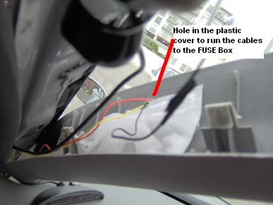 |
Drill a hole in the A pillar panel cover at the point where you want to place the LED Scanner. The hole is where you will run the wires from the scanner. At this point route the scanners' wires through the hole. |
Step 3: Connecting the LED scanner.
(Click on image to open up in full size)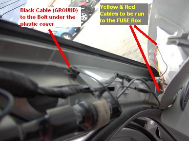 |
The LED Scanner has 3 cables: a RED, a YELLOW and a BLACK. The wires are not that long and therefore you need to add more wire (Yellow and Red) to the existing one to extend the reach. For this setup the modifier used left over wires from an existing mod, so the colors do not match in the images. The red cable turns into the black cable and the yellow cable to the Black/White cable in the images shown. But for simplicity purposes, I will refer to the correct wire color as it should be. Connect the Black wire from the scanner to a grounding point such as the bolt under the plastic cover. Run the remaining Yellow and Red wires to the Fuse box. |
(Click on image to open up in full size)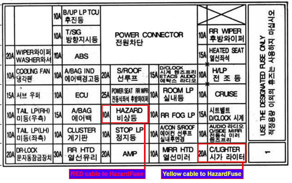 |
Once you have routed the 2
remaining wires to the Passenger Compartment Fuse Box (PCFB) area, they will
be connected as follows. |
(Click on image to open up in full size) |
You can use this image to locate the actual fuse locations for the setup. The 10 Amp Hazard fuse is at
position # 15, and |
(Click on image to open up in full size)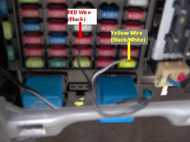 |
As stated previously, The Red wire gets connected to the 10 Amp Hazard fuse. The Yellow wire to the 20 Amp Cigarette Lighter Fuse. You may need to use a needle nose pliers to insert the wires. |
|
|
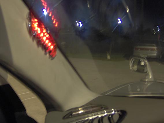
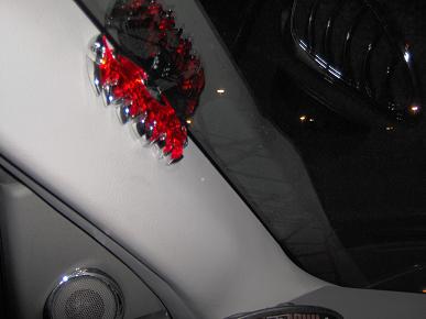
The LED should turn on when you turn off the vehicle, and turn off when you start the vehicle.. |
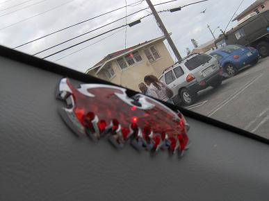
Final Views: (Click on image to open up in full size)
| Day time view - Close-up | Drivers view | Night Time View - Close-up Off | ||
 |
|
 |
||
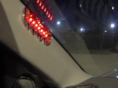
| Day time view - Close-up | Drivers view | Night Time View - Close-up On | ||
 |

|
 |
||
| Blue color version | Night Time View - Close-up On | |||
|
|
|
This site was last updated 02/08/06